Hub motor wiring (6 wires vs 8 wires?)

job

1 mW
Joined
May 6, 2017
Messages
11
Hi all,

I've recently acquired a geared hub motor and am looking to replace my existing gearless hub motor (for more torque and reduced top speed), but am having some issues wiring the controller to the new motor, both are 500w and 48v

From what I have read, there should be 3 thick phase wires and 5 hall wires (3 hall and 2 power) for a total of 8 wires.. but this new geared motor has only 6 wires (3 thick phase wires, 3 hall? wires? red, black and white)

Basically
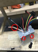
1. Controller 3 thick wires (Green, Yellow, Blue) and 5 smaller wires (red, black, blue, yellow, green)
2. New motor 3 thick wires (Green, Yellow, Blue) and 3 smaller wires (red, black, white)

I've tried wiring the phase wires and 5 and 3 smaller wires to various combinations (leaving 2 wires free), nothing makes the motor spin or react.. perhaps i am missing something?

Attached is the image of the motor

Cheers!
 

Attachments

  • wiring_help.jpg
    wiring_help.jpg
    115.3 KB · Views: 5,724
I'd try:

Phase wires to phase wires
Red to +5
Black to ground

Blue, yellow, green to H1, H2, H3 (might have to try a few different combinations of those)

The exhaustive way to do this is connect +5 and ground to +5 and ground and try spinning the hub. You should get sensor outputs from H1, H2 and H3. (You need a scope to see this easily, but can use a meter if you spin slowly.) That will tell you the order of the sensor outputs, and verify that they are all present and working.
 
Hey bill,

Thanks for your reply! There's no h1 h2 h3 wires on the motor, does that mean I have to solder my own to the h1 h3 h3?

This motor has been taken from another, the original controller really does only take in 6 wires (instead of 8)

Cheers!
 
My guess is that's a sensorless motor and the 3 small wires are for powering a single Hall sensor for wheel speed signal.
 
Hi Ykick,

Hmm.. i suspected it is a sensorless motor.. what would be the best way to get this to work with my current setup?

Cheers!
 
The legend on the circuit board tells you what Ykick says, with solder joints to GND. +5, and SP, while H1,H2,and H3 are empty.,

You cannot get it to work with your current setup, unless your controller can work sensor or sensorless.

Edit: Well, you could install three Hall sensors, and the wiring. The empty holes are there on the circuit board .... Nah ...
 
The three small wires go to that single hall sensor in the motor; it's just a wheel speed sensor. It won't work for the controller's hall sensor wires. It uses a power, ground, and signal wire (don't know which color is which but you can trace that out from the PCB), if you want ot use it with a bike computer or cycle analyst or other speedometer.


If your controller is sensorless, you can use the new motor. Otherwise you cannot use it without getting a new controller. (unless you install hall sensors like Honeywell SS41 into the PCB inside the new motor, and add the H1/H2/H3 wires). This will only work if there are already slots in the motor's stator laminations for the sensor to fit ino. If there arent', then you could notch the motor for them but this has a risk of shorting laminations as well as slipping and cutting motor windings. :/

Assuming you have a controller that can work sensorless:

Leave the small wires unconnected, and only connect the phase wires.

Then use the "learn" function of your controller (if it has one) to have it decide what order to use the phase wires in, and make the motor spin in the correct direction.

If it doesn't have a learn function, hook up the 3 phase wires in whatever order you like, and see if the motor spins. If it doesn't, then swap any two phase wires, and then the motor will spin. If it still doesnt', then your controller won't work with this motor.
 
Hey all, I've gotten a sensor less controller, attached is the picture of it

Could anyone tell me what does the twin single gray wire and orange white pair wire does?

Everything else matches up perfectly with the existing setup but these remain

So basically just connect it up to the 3 phase wires and it'll spin?

Cheers!
 

Attachments

  • unnamed.jpg
    unnamed.jpg
    112.2 KB · Views: 5,651
The single gray is commonly the speed limiter. Plugged together makes it go slower. Orange white might be brake cutoff maybe?
 
Voltron said:
The single gray is commonly the speed limiter. Plugged together makes it go slower. Orange white might be brake cutoff maybe?

Hi Voltron, yeah the 2 grey wires connect to each other..

Hmm I wonder where the speed sensor is, I could tap the red and black wires for power, that leaves a single white wire which is presumably a speed sensor..

Cheers!
 
Back
Top