identify chinese controller

molokai

10 µW
Joined
May 25, 2020
Messages
6
Hi, I have 2 controllers from (possibly) same manufacturer. but I'm having some issues with one of them, so I am searching for some data on them. Anyone have some information about them?

The PCB seems pretty standard. many things are like any infineon/Green/kelly etc controller. But some PCB markings are a complete mystery to me.
For example, there is a purple wire marked YB on the PCB. no idea what it is for.
There are some minor differences between the two, but the PCB:s are practically identical. just some different cables/connectors.

1500w controller
2020-05-25 22_43_28-Window.jpg

Here is a Yandex translation from the 1000w controller
company1000.png
controller1000.jpg

I can of course take some pictures of the PCB if needed

Thanks
 
Never seen them, but what specific issues are you having?
 
On the 1500w the voltage immediately drops to 0v as soon as I connect the battery. like if there was a short between the poles. but I measured so many times. no short. Tried Amps in series as well, but never got my slow instrument to register any current, it simply goes from 60+v to 0v in ms as soon as I hook up the controller. I have disconnected everything except Throttle, ABC to Motor(and at times, the alarm.) still same issue. so it happens even when "ignition" is off. So I am more an more thinking it might be the BMS.
I rebuilt the battery from a 4P to 10P. so there is quite a lot more juice in it than before. But the Fuse I is use quite low, lower than the maximum specs of the BMS, so I would think it would blow first. but it does not.

I quickly built a 16s1P this morning. and without a BMS. Will update as soon as I have tested.

some other details:
if I push the bike forward(even without battery) Regen brake fills the controller with with enough power to start the alarm sound. I can even shut it off with remote. So I suspect the controller is quite ok.

I really frocked up the dashboard/speedometer,headlight cables when I tried to "hack" the 45km/h limit.
in my defense, that this was before I discovered this wonderful forum. :)
Could it be a mandatory component or is this not likely?

It had a Bluetooth receiver (the headlight/speedometer/lights part) that I though could possibly be used to program the controller.
But I have basically drawn the entire circuit into a complete schematic(BT board) and to me, it simply looks like a bluetooth Mono speaker. so quite useless really.

Last question. Key ignition was included in the headlight+LCD part. it had 3 wires. Red, Orange and black .
the key has 2 positions, first one only starts the bik, second one also turns on the light.
I did some research and I determined that the most common way, to put the controller in ON, is to hook Orange to Plus(red), or is this incorrectly assumed?
 
molokai said:
On the 1500w the voltage immediately drops to 0v as soon as I connect the battery. like if there was a short between the poles. but I measured so many times. no short. Tried Amps in series as well, but never got my slow instrument to register any current, it simply goes from 60+v to 0v in ms as soon as I hook up the controller. I have disconnected everything except Throttle, ABC to Motor(and at times, the alarm.) still same issue. so it happens even when "ignition" is off. So I am more an more thinking it might be the BMS.

This means the BMS is shutting off to protect the pack from something. If it has a low cell, below LVC, then you may get a "ghost voltage" (leakage) on the output, that makes it *look* like the battery is on and working, but *any* load will drop that to nothing, because the BMS can't provide any current to sustain the voltage under the load.

It could be a short in the controller, but if you've measured that, and there isnt' one, then its' probably not an overcurrent trip in the BMS.

So probably an undervoltage (LVC) problem, where one or more cells in the pack are below the BMS's cell-level LVC.

But if the problem doesn't happen using the other controller with this particular battery, then there's still something different about the first one that overloads the battery and shuts it down. It may still be a problem in the battery, not the controller, where the battery is just incapable of handling the demands of the first controller, but can handle the second.


if I push the bike forward(even without battery) Regen brake fills the controller with with enough power to start the alarm sound. I can even shut it off with remote. So I suspect the controller is quite ok.
Probably controller is ok then.

I really frocked up the dashboard/speedometer,headlight cables when I tried to "hack" the 45km/h limit.
Could it be a mandatory component or is this not likely?
I don't know. If it has a screen where you select PAS levels, etc., then it's likely the controller will only operate in the default lowest mode without it. It may also require finding the "ignition" wires in the display cable if the display is what turns on the controller, to use the controller without the display.


It had a Bluetooth receiver (the headlight/speedometer/lights part) that I though could possibly be used to program the controller.
But I have basically drawn the entire circuit into a complete schematic(BT board) and to me, it simply looks like a bluetooth Mono speaker. so quite useless really.
Don't know on the BT; the only thing I've seen them for on controllers so far is for displaying on things like Eggrider or a phone, or for programming and setup.

Key ignition was included in the headlight+LCD part. it had 3 wires. Red, Orange and black .
the key has 2 positions, first one only starts the bik, second one also turns on the light.
I did some research and I determined that the most common way, to put the controller in ON, is to hook Orange to Plus(red), or is this incorrectly assumed?
Don't know by color (those coudl literally be anything). You'd have to look inside the controller itself to see where those wires go first, because if you connect the wrong ones, you can completley destroy the controller's electronics (Keyswitch / ignition (KSI) wires have battery votlage on them...but the rest of stuff in displays is usually 5v or less, and would be destroyed by connecting to battery voltage.

Inside the controller, one of the KSI wires will come from the main battery + wire connection. The other KSI wire will go to the same general area, but to the input of the low-voltage powersupply (LVPS) of the controller, that powers the brain section. The LVPS typically has a large resistor on it's input, but some of them use a small SMPS (switching) circuit instead. On the controller below, the two KSI wires are the thinner red ones at the left, one near the bottom edge of the circuit board, and one passing behind the big capacitors along with the main battery wire.
file.php
 
Thank you. very helpful. I have not tried the faulty battery(confirmed it a few hours ago) on any other controller.
since the pack has close to 100 18650 and I soldered it together, did not have a spot welder at the time. I know, cardinal sin most likely, but I have 8000 cells lying around here, all completely free. So I will just put the whole pack in the "to be tested" pile of cells and create a new one.

The 1000w controller(and scooter) belongs to a friend. I only use it as a reference to rebuild my own.

I totally disassembled the 1500w fat-scooter last year. did it properly, labeled every cable and so on. but I expected to rebuild it in a matter of days, not 8months later. so the outside moisture made all labels pretty much unreadable.
I took some notes for the LCD-Hub when I disassembled it. but many months later, I think it just got thrown in the thrash at one of the many Garage cleanups since then. Since Corona has pretty much made any deliveries from China 2-3 months longer than normal. summer will be over when I receive the new 2000w controller i ordered.
so this one, will be replaced at some point.

The LCD-cluster is quite simple really. if i put + and - directly on the battery, it will display the proper voltage(even the faulty pack) it also seems to read/calculate speed from the hall sensor(s). if I remember correctly it used only one phase, too dark now for me to check.
it also blinked in the display when I used the turn signals.. which is odd since the scooter had no external lights for this purpose :)

There is one small difference between the two scooters, besides the 500 extra watts. mine had a 16s4p battery. the other one has a 17s4p battery.
not sure if this is some way to get it to run slightly faster?

Both scooters were purchased very cheap second hand. previous owners listed mine as broken battery, possibly controller, it was a gamle if it would be a bargain or not.
I fixed mine (the battery) the same day I got it. surprisingly, it had a very simple explanation why it did not charge. not really a fault.
The scooter must have been left with something ON for months is my guess. pack had 10-14v. far too low for the charger to start any charging process. when I analyzed the issue, I noticed that each time I connected the charger and measured the Voltage. it increased by a volt or two. so I connected/disconnected the charger 30-40 times , viola, normal charging process started.
I used it for many months, without any issues whatsoever. all issues now, I must admit, I caused myself :) my reason=did no like the fixed speed limit.
it was obvious to me that it could run much faster, something was stopping at 45km/h.


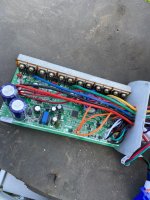
Took some photos today on the PCB.
my own guesses: it seems that the cluster of orange cables (labeled VK1) in the middle bottom part that seems to be used for several switches (horn, ignition etc) basically shorting VCC to the orange cable and turn controller on, honk the horn and so on. etc.
the 3 speed swith seems to use the standard K1,K2 labels.

TS is somewhat of a mystery to me. there is a TS+, a TS and a TS-, only TS and TS+ is used.
I am 99% sure were to connect it, but what is TS short for? and why is only TS and TS+ used?

The grey cable that shorts the SL connection, what is it? it goes to a 2 pin connector, one orange and the grey. if it was a VK1 orange cable, I cant recall at the moment. can check tomorrow. but if someone already know what it is, let me know

the last puzzle: the purple mystery YB cable. just a single pin connector. no idea what it is used for.
in both scooters it is not connected to anything.

IMG_1056.jpg
IMG_1048.jpg
 
this is the sa model of KSI
https://www.aliexpress.com/item/33056422337.html?spm=a2g0o.detail.1000014.9.597290dcUhHZyA&gps-id=pcDetailBottomMoreOtherSeller&scm=1007.14976.158757.0&scm_id=1007.14976.158757.0&scm-url=1007.14976.158757.0&pvid=f14bc4c6-c9ea-4d0d-8053-96ed34a850ce&_t=gps-id:pcDetailBottomMoreOtherSeller,scm-url:1007.14976.158757.0,pvid:f14bc4c6-c9ea-4d0d-8053-96ed34a850ce,tpp_buckets:668%230%23131923%233_668%23808%234093%2341_668%23888%233325%2316_4976%230%23158757%230_4976%232711%237538%2328_668%232846%238116%23958_668%232717%237558%23103
 
molokai said:
There is one small difference between the two scooters, besides the 500 extra watts. mine had a 16s4p battery. the other one has a 17s4p battery.
not sure if this is some way to get it to run slightly faster?
Dunno. Unless that's LiFePO4, then neither of those is a common "ebike" standard (usually they'd use 13s = 48v, 14s = 52v, 20s = 72v, etc). But 16s is a 60v, which is a voltage seen on a fair number of scooters (usually using 5x 12v SLA batteries).

If it's LiFePO4, then 16s is a "52v" battery.


But adding a cell can increase the wh total capacity of the pack, increasing range, or it can increase teh voltage which does increase the theoretical top speed (actual speed depends on if you have enough watts to go that speed, and whether the controller is locked down to prevent that). But it puts the controller electronics just that much closer to the edge of their specs, which makes them less reliable, less predictable whether something close to the edge will fail.


The scooter must have been left with something ON for months is my guess. pack had 10-14v. far too low for the charger to start any charging process. when I analyzed the issue, I noticed that each time I connected the charger and measured the Voltage. it increased by a volt or two. so I connected/disconnected the charger 30-40 times , viola, normal charging process started.

That means the BMS on the pack is either damaged or a bad design, that doesn't protect against overdischarge, because if it did, it would not have allowed any of the charging to happen at all.

Overdischarge-recharge protection is important, because cells that have sat a long time under a couple of volts can be damaged in ways that leave them vulnerable to starting a fire once current is flowed thru them again. I recommend never using any cells that dropped that low, simply because you can't know if they will fail that way or not until they do fail that way, and it's a little late then, especially if the battery is indoors at the time. (or on a scooter or bike or whatever that you wanted to keep).


my own guesses: it seems that the cluster of orange cables (labeled VK1) in the middle bottom part that seems to be used for several switches (horn, ignition etc) basically shorting VCC to the orange cable and turn controller on, honk the horn and so on. etc.
It's possible. Not familiar with those.


TS is somewhat of a mystery to me. there is a TS+, a TS and a TS-, only TS and TS+ is used.
I am 99% sure were to connect it, but what is TS short for? and why is only TS and TS+ used?
It could mean Torque Sensor. Many of those have a power supply, an analog voltage, and a cadence sensor. So TS+ might be the power supply, and TS the signal for cadence, and TS- might be the analog torque signal. Then if there is a cadence sensor but no torque sensor, it might just use the cadence input and power to run it (and ground from somewhere). One of them could be for direction of rotation of cadence sensor, too.

It could also be a temperature sensor. Or it may have nothing to do with anything starting with those letters, just like many functions. :/


The grey cable that shorts the SL connection, what is it? it goes to a 2 pin connector, one orange and the grey. if it was a VK1 orange cable, I cant recall at the moment. can check tomorrow. but if someone already know what it is, let me know

the last puzzle: the purple mystery YB cable. just a single pin connector. no idea what it is used for.
in both scooters it is not connected to anything.
Dunno on either of those, but SL migth be Speed Limiter (or, as noted, not have anything to do with S or L words).
 
Hi, some comments

That means the BMS on the pack is either damaged or a bad design, that doesn't protect against overdischarge, because if it did, it would not have allowed any of the charging to happen at all.

Overdischarge-recharge protection is important, because cells that have sat a long time under a couple of volts can be damaged in ways that leave them vulnerable to starting a fire once current is flowed thru them again. I recommend never using any cells that dropped that low, simply because you can't know if they will fail that way or not until they do fail that way, and it's a little late then, especially if the battery is indoors at the time. (or on a scooter or bike or whatever that you wanted to keep).
Agreed, but I forgot to re-mention that the current battery, is with another BMS and different cells. I only mentioned this part because of the Bargain aspect :-D
Last night I spent some more time on the current pack, found 2 cells that probably got destroyed when I soldered the damn thing(which I know, is really really dangerous and stupid. But I had no spot-welder at that time)


It could mean Torque Sensor. Many of those have a power supply, an analog voltage, and a cadence sensor. So TS+ might be the power supply, and TS the signal for cadence, and TS- might be the analog torque signal. Then if there is a cadence sensor but no torque sensor, it might just use the cadence input and power to run it (and ground from somewhere). One of them could be for direction of rotation of cadence sensor, too.

I think your first guess is correct. I have a vague memory that this was one of two connectors that went to the speedometer/LCD cluster. So it could be measuring RPM:s in order to display correct speed.


Dunno on either of those, but SL migth be Speed Limiter (or, as noted, not have anything to do with S or L words).
I think it has something to do with regen motor breaking. I am sure it is not the Speed Limiter.

The Speed limiter is the K1/K2 thing I mentioned earlier. there is no doubt about that one. the Cable goes to the 3 position switch and uses 3 cables, one to GND, one to K1 the last to K2, a combination between them sets the 25%, 50% 100% power setting.
Same colors on both ends and quite unique(also somewhat readable label left)

only a few cables remain to be properly connected.
Throttle 3 pin contact
Controller power on, also a 3 pin contact.

if you recall, the lock had 2 positions.
first position = start controller
second position = also enable lights.

I measured the lock positions with a multimeter. short combo looks as follows:
First position=short 2 poles
Second Position= short all 3 poles

Edited/removed some parts.. I found a label, underneath one of the shrink wraps.. I facepalmed myself a few times I can tell you... Some details came back to me of the disassembly 1 year ago. I think it will make more sense in my next post.
I was was incorrect on a few things.

I am reverse engineering the PCB, cable by cable into a very simplified schematic.
will post it later when finished.. Some cables are a no brainier, but some I think I might need some helpful hints to sort out.
regarding the Blue contact .. The hidden label I found was indeed on the mystery blue 3pin contact.
I had put the label on only 2 of the 3 cables, deliberately. the label said... "BT module".. and I remembered that the LCD cluster had several loose and twisted cables together with other instruments. pretty crappy setup to begin with.

I can live without the Bluetooth, LCD, horn, Lights and so on. I only need Throttle.. and maximum speed. :mrgreen:
it perhaps makes more sense when I send the schematic
 
Back
Top