Infineon has REGEN BRAKING (and more)

methods said:
Like Philf eluded to...
It is nice that they are "targeting" 3.8mOhms but in reality, a few hundred microOhms (3.8, 3.7, 3.6, 3.9...) is the difference of how the shunt is soldered.
If jack does it you get 3.5mOhms
If Jill does it you get 3.7mOhms

If you want accuracy you need to calibrate the shunt yourself.

-methods

I think they both must have had a go at it to get it down below 3.2mOhms.
Maybe I can mend it with some "vinegar and brown paper" :D
 
That is quite a compelling argument you have there Knuckles.
Did you learn that form of debate at Jr College?

Reminds me of how DeafScooter reacts when someone says something that upsets him....

Is there something you would like to talk about? :roll:

-methods
 
I am BUSTING YOUR BALLS Bro!
 
That you are.

I must admit that pushing the "poser" button is a good way to piss me off. :wink:
At least you did a good job of it.

Who was it that started in with that last time? Mathurin?
I am going to present you with the same award he earned

Dedicated to Knuckles for attacking me unprovoked :mrgreen:
.
.


-methods
 
So are you saying ... YOU ARE NOT A KOOK?

I'm just trying to clarify before I add sound tracks to your vids. The one in the "gulley" made me CRACK UP big time! :D

(I like your vids btw ... funny as all f*ck ... they are just ... well ... kookish ... but very nice) :roll:

That ass-clown looks ... well ... he looks alot like YOU! :shock:

Anyway ... I posted a "method" for accurate shunt calibration a while back on my Infineon Tech thread ...
http://endless-sphere.com/forums/viewtopic.php?f=16&t=7361#p110932
(near the bottom of the post)

Keep "Dropin in" bro!

-Peace Mutha F*cka
 
methods ...

I am not attacking you at all.
I am Busting Your Balls BIG TIME.

Sorry. I just could not help myself.

Anyway. You Ride. Your Cool. That works for me.

Man YOU GOT SOME SERIOUS BUG EYES!

[youtube]Vz4KOBcqG1o[/youtube]
More ...
http://www.youtube.com/watch?v=1HYgSdW8N40
 
Knuckles said:
So are you saying ... YOU ARE NOT A KOOK?

Nope, same as before.
Never made any claims to not be a poser.
My skills are money making skills, not bike riding skills. :wink:
You want to whip um out and see who's paycheck is longer? :mrgreen:


Knuckles said:
Anyway ... I posted a "method" for accurate shunt calibration a while back on my Infineon Tech thread ...
http://endless-sphere.com/forums/viewtopic.php?f=16&t=7361#p110932

Well thats a great "method"... To bad it has nothing to do with what we have been talking about for the last 20 posts.
You can calibrate that undersized shunt till the cows come home.. . . When it starts burning 10W let me know how accurate it is :roll:

Christ. . . All I tried to do was post a little spread sheet info on the power that would be pushed through a single M shunt if it were used on a modified controller.


And btw, since we are criticizing each other now:

You should update that Infineon tech thread you seem to be so proud of. The Technical content has errors.
Example:

You call out the CA pin 6 as going to the brake line.
That is like using a bubble level for a baseball bat
Pin 6 is a variable low level pull down and should be tied to the throttle line via the cathode of a diode.
This will allow the CA to perform the full set of functions and not just slam on the brakes.

I have lost my taste for your thread.
I am sure I can navigate the Infineon without your gracious help :lol:

-methods
 
fechter said:
methods said:
.


-methods

We could have used that one a while ago. I'll add it to my collection along with the fried guinea pig. :mrgreen:
hi
is there an award for spaming a thread so far off track it is unreal ,if so im sorry methods i award you it this is a thread on infineon regen (mainly the 12 fet as that is what we work with) it is not a thread on how if you take a 6 fet infineon change the fets to 100+V, 100+A then try to reprogram the controller with the software that is made by the designers of the board turn round and say the shunt wont work it must be changed.

You should start your own thread not spam up other threads with non relivent information. you chose your subject matter then post links in threads that you think will find it of use then get out and stick to your own thread on your subject.

so untill the award can be found I award you the thread spamer gold award to be replaced with a picture when I find one.


Now methods start your own thread from what you have just said you are going please do


Geoff
 
Everybody chill.

methods said:
The reason I take shunt calibration so seriously is because I have been burned :D

Usually we think of the shunt as being used for the current limit or maybe on the CA for current display

To me, the true value (and danger) of a shunt is using it to keep track of Ah usage (especially when you run an insane Lipo time bomb with no BMS). With my 100V 100A 5305 I needed to have a very good idea of Ah used and Ah left. Often times on rides it would take me 3-4 Ah just to get home.... If my shunt calibration was off by just 5% that means I am walking :(

It would be good to test the temperature drift of a soldered shunt. Good point Philf.
I have seen the peltier effect after long hard pulls of over 80A but it usually is only a few hundred ma offset.

Where do you buy shunts?
I would agree that 1mA is a good round number to use.

-methods

I want to know Why methods is so CRAZY EYES about this.

AND ... HOW on earth is the Infineon shunt "burning" 10 Watts?

· Shunts
The latest Infineon pcb is fitted with a consistent shunt.
The standardized shunt value is approximately 3.8 mOHM.

So ... V = I x R ... V (across the shunt) = 50 amps x 0.0038 ohm = 0.19 volts
And ... V x A = W = 0.19 x 50 = 9.5 Watts.

Holy Sh*t! Your right!

That is one "HOT ASS" shunt! :shock:

You still have BUG EYES MoFo ... But I see your point now.
 
Thanks Kunckles
But I thought your 12 fet version has 2 shunts in parallel?
That should be 1.9mOhms so all good right?

Geoff,
It is obvious that you did not, and still dont, understand the information that I was trying to convey. Never once did I tell you that "your shunt would not work". I pointed out a subtlety that seems to be lost on you.

Man, you guys are possessive!
Someone should have warned me not to step on the toes of the Infineon gods! :D

-methods -> God of Spam!
 
Everybody Love Everybody... :mrgreen:
 
Chill Chill Chill!

Gosh! WHY CAN'T WE ALL BE FRIENDS?

Method-Shaped-Shunts.jpg
The scoop is that BOTH these shunts measure APPROXIMATELY 3.8 mOHM. As measured together.

SHEEEET!

btw ... I CAN prove you wrong. GOSH! Be part of the solution. Not Part of the problem Bro!
50 amps! So when is the last time you pulled 50 amps continuous?

- :roll:
 
nomad85 said:
Everybody Love Everybody... :mrgreen:
WORD!

I am laughing my Ass Off! :D

AND LOVING IT! ...

[youtube]rLxTpsIVzzo[/youtube]
 
So many tech people with strong characters, all in one place together! You guys make for good laughs, that's for sure! I just wish I had high speed to actually see those youtube videos people keep on posting everywhere.

[more off-topic spam I know... but hey, even knuckles is pretty darn good at that in his own threads, and Methods is doing good, so I decided to pitch in a bit just here to infuriate the gods... or Leonidas, whichever has a shorter temper!]
 
solarbbq2003 said:
can i bring up the 6 fet board, anyone know which is low voltage resistor?
hi solarbbq
That is alright none of the people mouthing off about the 6 FET board seem to have started a 6 FET Infineon thread so sensible questions and contributions are still welcome and always will be.

Down to the answer to your question, now I /we already know a lot about the 12 FET board, well the designers were sensible all the boards have been designed from the same block circuit design with only minor changes between each board, the printed circuit is different but each section can be found on each board, the components may change but the result stays the same. Where possible components have been named the same on different boards that are doing the same job even if the component is different, as a result knowing where the LVC resistor is on the 12 FET board I could soon find the LVC resistor on the 6 FET board.

So and sorry to be a bit long winded on the way I worked it out, the LVC is our old friend R12 now what value this is on a 6 FET board I do not know though I think it will be 1k2 ohm the tracks follow the same layout as on the 12 FET board there is an identical connection between R10, R11, R12, C9 and Vcc-L.

6 FET resistors.jpg

A replacement resistor will be more difficult to fit than on the 12 FET board but still possible.

Geoff
 
thanks geoff very much appreciate good to see similarities between the boards
Another question! this might have been covered before: but I cant find if it has
the max amps setting on the parameter designer.exe program are:
1. phase current
2. rated current
I'm assuming rated current you set to whatever you want the max amps to be, and phase current is a cut off level substantially higher than rated, also suposing that phase current in pulsed current over short time frame.
Anyone know what keywin is setting for these two values in the 72volt 50amp controllers?
 
solarbbq2003 said:
thanks geoff very much appreciate good to see similarities between the boards
Another question! this might have been covered before: but I cant find if it has
the max amps setting on the parameter designer.exe program are:
1. phase current
2. rated current
I'm assuming rated current you set to whatever you want the max amps to be, and phase current is a cut off level substantially higher than rated, also suposing that phase current in pulsed current over short time frame.
Anyone know what keywin is setting for these two values in the 72volt 50amp controllers?
hi solarbbq
the phase current wants to be about twice the rated current
the MAXIMUM rated current a 6 fet board can handle is 25A
over this regardles of altering the shunt to take the higher amps the board will not take it you will start to get tracks lifting
so if you find you are getting a constant power draw of over 25A change to a bigger controller
the actual values that are used may depend where the controllers have come from, if bought direct from keywin from the ecrazyman ebay site it will have one setting, if bought through knuckles the value may be diffrent and if bought in the UK from Team Hybrid a difrent value may be found again.
This is not due to bad sales practise but we have each found our own values (I set the values for Team Hybrid) I will try to get keywins values so we can standardise any controller sold via me I Keep a record of the settings file and can send them to anyone if the want Team Hybrid has just started selling though.

looking at the ebay site the 72v controller is set at 45A knuckles sets to 50A he might be a better one to answer this question, if you got through him he must know, he reprograms all hs controllers as do I.

Geoff
 
thanks again geoff, I got them straight from xie cheng, xie cheng can supply controllers all finished not just the boards,
but they wont do mods like put the 5 pin connector on for programming unfortunately, and they have limited mosfet type selection
so following on question: can the parameter designer.exe program display what the current settings of the controllers are?
I mean can it transfer from controller to computer to display current settings?

(i've got these controllers in china office but haven't got them out to australia as yet so cant do any hands on until I get some out here)
 
philf said:
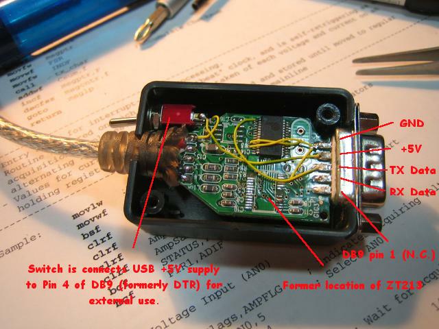
USB%20Diagram.jpg


Hopefully this makes it clear enough for anyone who has a hankering to give it a whirl. Like I said, eBay is FULL of these cables (just use "usb rs232" as a search argument).

I followed in your footsteps Philf.
It is confirmed that you can program the 6 fet version with RX & TX @ 3.3V
I took an RS232 to 3.3V converter that I had and tapped +5V off pin 1 of the max chip

Wired my box with the first connector I had around, a 7 pin JST-XH
Perhaps later I will swap it out with a 4 pin.

9CWheel_n_6fetmod_023.jpg

Plugged in the programing cable
Hit transmit on the software
then turned the controller on.
Firmware uploaded in about 2 seconds

Good deal.

-methods
EDIT: Corrected "TTL to 3.3V" to be "RS232 to 3.3V"
 
I just happened to have an RS232 to 3.3V converter
Was not sure if that would work, it does.

-methods
 
Back
Top