Infineon has REGEN BRAKING (and more)

Mike1 said:
Also, is there anyway to wire in the high level brake wire?
Thin Yellow Wire for (+) eBraking (ie connect thin yellow wire to anything + ... not GND) ...
Refer to ... http://98.131.176.65/endless-sphere/Infineon_Wiring.jpg
 
Mike1 said:
Hi Phil, thanks for the reply.
Yes there are 15 P75NF75 mosfets. I thought there would be some multiple of 6 so a little confused by that.
Mike.
This controller appears to use 2 high side FETs and 3 low side FETs per phase. Seems odd at first, but actually this can be good specially if the controller is being used often at partial duty output (meaning at partial throttle and/or while the contoller is doing current limiting). Not too usefull for someone spending most of their time zipping along at full speed and full throttle, but good for going up hills at partial speeds. The Low side FETs in this situation work harder than the high side FETs, making such a design choice logical.

BTW, has anyone else spotted what looks to possibly be a switching power supply on this controller? Mike, could we have a close up picture of the area of the board around where the smaller red wire goes? With a bit of an angle so we can see the chip number of the heatsinked part, or maybe just tell us what it is? Also, can you make out what number is on that surface mount part, numbered "U1"? Thanks!
 
Hi Knuckles,

The picture for the controller on Ebay didn't have the yellow wire but it has arrived today and sure enough the yellow wire is there so should save me a bit of work.

Mike.
 
Hi ZapPat,

I'll get that info posted asap. The earlier photo is of someone else's controller so I have asked him for the component numbers. This is the one my scooter is meant to have but mine was supplied with the wrong controller and wrong batteries. I am still waiting for the replacements from the supplier.

Mike.
 
Knuckles said:
Shout out to philf ...

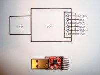
Keywin just bought these local in Shenzhen (cheap) ... He says they worked perfect ... USB-TTL for programming the Infineon.


exactly the same dohickey i bought on ebay for my laptop USB to talk directly to the TTL port on my V2 cycle analyst. now i just have to figure out how to connect to my Infineon.

rick
 
cool! :D
rkosiorek said:
exactly the same dohickey i bought on ebay for my laptop USB to talk directly to the TTL port on my V2 cycle analyst. now i just have to figure out how to connect to my Infineon.rick
should be easy peasy.

this I want to know.

-K
 
Regen Braking FYI ... http://endless-sphere.com/forums/viewtopic.php?f=2&t=8457&p=132306#p132306
 
ZapPat said:
Mike1 said:
Hi Phil, thanks for the reply.
Yes there are 15 P75NF75 mosfets. I thought there would be some multiple of 6 so a little confused by that.
Mike.
This controller appears to use 2 high side FETs and 3 low side FETs per phase. Seems odd at first, but actually this can be good specially if the controller is being used often at partial duty output (meaning at partial throttle and/or while the contoller is doing current limiting). Not too usefull for someone spending most of their time zipping along at full speed and full throttle, but good for going up hills at partial speeds. The Low side FETs in this situation work harder than the high side FETs, making such a design choice logical.

BTW, has anyone else spotted what looks to possibly be a switching power supply on this controller? Mike, could we have a close up picture of the area of the board around where the smaller red wire goes? With a bit of an angle so we can see the chip number of the heatsinked part, or maybe just tell us what it is? Also, can you make out what number is on that surface mount part, numbered "U1"? Thanks!

Hi Zappat, I finally got those component numbers.
The heatsinked part is a LM317T
U1 has the following on it.

CY8C24423A-
24PVX1 0719
B 02 CYP 62569.
 
philf said:
Hiya Mike!

Welcome!

I can't help with identifying what your current controller is, but it's intriguing that there appear to be 15 (!) devices along the rib. Are they all the same? Looks almost like a "3 to 2" scheme for each phase.

You've highlighted a pet peeve of mine with respect to the Infineons, though. You can program 'em, but (unless I'm very badly mistaken), you can't recall the configuration that's in there. I find that bothersome, as it seems you have to load a "known" (to you) config into the things and experiment with the behaviour before you have a starting point. You have no idea how many, if any at all, parameters you changed with the first transfer. It would be sweet to be able to suck the current configuration out play with only the parameters of interest. :-(

Of course, it's possible that the firmware in the controller DOES support this, but the VB program that is currently available to do the programming doesn't bother supporting that feature. I've been tempted to bastardize a data logger onto the interface to see what actually gets sent back and forth between the PC and the controller during programming. Even knowing the bit rate would be a nice starting point, though :-(
Hi Phil,
My E-Crazyman controller arrived, it is a direct plug and play replacement for the original. Even the hall and phase wires match up, and the connectors are the same, so I suspect they may have come out of the same factory.
Finally made my programming cable today. Bought a little usb interface module on ebay.

do_dad.JPG

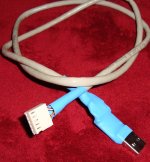
A bit of soldering and heatshrinking later and I had what might just do the trick.

cable1.jpg

I'll scope out the output tomorrow before plugging it in and testing it.

I'll also log the comms data and report back here. Without being plugged in to a controller all the software does is open the port, pump out three "8" characters and close the port. Then it repeats. Obviously waits for the controller to respond with some other character, looping the "8" back to it does nothing. Should know more tomorrow.

Mike.
 
cool.

btw ... Keywin builds EVERY controller he sells HIMSELF.

Keywin buys the "raw" pcb's from xie-chang (in bulk).
He also has the USB-TTL do-dads ... http://endless-sphere.com/forums/viewtopic.php?f=2&t=8317&st=0&sk=t&sd=a&start=75#p128713
 
Knuckles said:
cool.

btw ... Keywin builds EVERY controller he sells HIMSELF.

Keywin buys the "raw" pcb's from xie-chang (in bulk).

Wow!

Is that right? The quality is outstanding, so I've gotta guess that Keywin has (or has access to) some decent gear for placing and reflowing the SMD parts. I've been thinking of trying a skillet :) Works for the guys at SparkFun :!:
 
Keywin has tinning ovens. He also wants to make the pcbs himself.

SUPPORT YOUR LOCAL CHINAMAN! :shock:

http://en.wikipedia.org/wiki/Chinaman
 
Success. The cable works a treat. I scoped it out first, it gives a 3.3 volt signal.

Loaded up the settings file that Keywin sent me so that I didn't change anything, hit the transmit button, plugged it in and away it went.

Below is the conversation the pc has with the controller.

Port opened by process "Parameter Designer.exe" (PID: 2868)

38 38 38 888

Port closed

Port opened by process "Parameter Designer.exe" (PID: 2868)

38 38 38 888

Port closed

Port opened by process "Parameter Designer.exe" (PID: 2868)

38 38 38 888

Port closed

Port opened by process "Parameter Designer.exe" (PID: 2868)

38 8

Answer: 19/02/2009 11:22:33.03764 (+0.0000 seconds)

55 U

Request: 19/02/2009 11:22:33.24064 (+0.2028 seconds)

02 0F 33 25 C7 04 CE 00 83 83 83 0A 96 00 01 06 ..3%Ç.Î.???.?...
68 6B 00 00 00 00 00 00 00 00 hk........

Answer: 19/02/2009 11:22:33.36564 (+0.1248 seconds)

55 00 U.

Port closed

Port opened by process "Parameter Designer.exe" (PID: 2868)

Request: 19/02/2009 11:22:33.91164 (+0.5460 seconds)

38 38 38 888

As you can see the program sends a series of "8"s until it gets a reply of "U", it then sends the setting info and the controller confirms it with another "U" and a NULL character. It then continues to send "8"s, I assume it is waiting for the next controller to program (production line style).

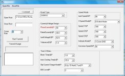
Here is the setting info I used.

settings.jpg
 
hi
that's the port my usb to rs232 uses.
well done for getting it to work now you will see just what the infineon do when programed diffrent ways.

Geoff
 
Hi Geoff,

I see you are in England, don't think there are many of us on here. I'm in the West Midlands. Got one of those Electric Mopeds that Firebox sell. Trying to make it a bit more practical. Where in England are you?

Mike
 
Mike1 said:
Request: 19/02/2009 11:22:33.24064 (+0.2028 seconds)

02 0F 33 25 C7 04 CE 00 83 83 83 0A 96 00 01 06 ..3%Ç.Î.???.?...
68 6B 00 00 00 00 00 00 00 00 hk........

Answer: 19/02/2009 11:22:33.36564 (+0.1248 seconds)


Cool. I'd guess all the parameters are in the hex string above.

Try changing one parameter at a time (like LVC setting) and look for where that change shows up in the string. From that it might be possible to figure out how to input settings between the selections in the pick list.

I've noticed in similar devices, the hex values do not correspond to decimal values, so there must be some kind of conversion going on there. How do you normally 'count' in hex? I know how to go from hex to decimal, but it seems there is some other standard way to increment a number in program code.
 
Cool.

As a programmer sort of guy, I'm wondering what the data rate is, and whether you were in sync with it.

"080808 (etc.)" is funny string to send when looking to sync up. You could shift that lonely bit, and depending on what's being used for start/stop bits, it could wind up being indistinguishable from some other repeating value. Most programmers pick values that have symmetrical bit patterns between the upper and lower nyblle for this purpose (I always use "A5A5A5" so there is NO mistake).

Terse conversation, though, wot?

Am I reading you correctly, and assuming that the screen shot of the parameters page you are showing is of the file that Keywin sent you? I've always wondered what he stuffs in there before the controllers leave his hands...
 
Hi Phil.

Yes I asked Keywin for the config file once I gave up on the idea that it might be possible to get the current config out of the controller. He said that the 40AMP limit would really be 48AMP as the shunts were measuring a bit low. Thought these M shunts were meant to be accurate.

I don't think there was any baud mismatch, all monitoring was taking place on the same pc as the software was running, I didn't use any kind of external monitoring.

I used this http://www.serial-port-monitor.com/index.html

Was the only one I could find that left the port unopened for the Parameter Designer to use.

Mike
 
hi mike
I'm in the midlands, nottinghamshire
Geoff
 
NOTTINGHAM!

(Apologies - everyone can already tell this is going to be off-topic, and - no - I'm not going to make any "Robin Hood" comments).

You must surely have had a pint here, at one time or other...

jersusalem.jpg


I know I have :).

Before my outfit got eaten by The French ( :evil: ), I used to be a somewhat regular visitor to your part of the world. Our offices nearby were in East Leake, with our (global) Head Office down in Slough. My entire family lot are from Sussex (since 1066 :roll: ), though I'm from Vancouver, Canada...

Hell, while I'm hijacking the thread...

robin.jpg


You can't get away from the bugger in Notts, can you? :lol:

And now back to our regularly scheduled program... (er, "programme")...
 
... and our regularly scheduled program contains more about *this*...

Mike1 said:
I used this http://www.serial-port-monitor.com/index.html

Was the only one I could find that left the port unopened for the Parameter Designer to use.

Y'know, that's actually a pretty cool piece of software. I'd wondered if anyone would hook the serial port (within Windows) at the driver level, but the Microso~1 people leave me cold on some things. GImme a 16 bit application window, and assembly language access to a 16550 at the register level, and I can do great things. Ask me to talk to some "driver" that obfuscates the existence of the actual hardware, and it's not fun any more. You're trusting that the guy/gal who wrote the driver got it perfect.

Anyways, I think the dialogue with Keywin on what was "in there" at the time of build-completion is a great thing. It *would* be nice to be able to suck out the current settings from an unknown controller. Even if only to see if they'd become corrupted by runaway code in the MCU.

Thanks, MIke!
 
hi
I've been past that pub never drank there though too many students for me, go past the statue often when I'm in nottingham, the bow and arrow keep on being stolen.

I said Nottinghamshire not nottingham I live in a market town about 14/16 miles from Nottingham, it grew up around the fact that it was a crossroads both land and water and as a result of it being there when rail came along that as well though not as major for rail now. our town grew up round what was always called "The Great North road" now known as the A1, "The Fosse Way" a road built by the romans now known as A46, the water link was the "Trent river" that boats carrying heavy loads could use.
now thats enough of off the subject we will get told off.

Geoff
 
Sounds like Newark to me.

Was working with someone from there recently. Was working at a place just south of you in Hinckley that makes much more powerful bikes than we are dealing with here :)
 
hi
thats it
Geoff
 
I've been playing with the programming again today. Anyone know what the Speed % settings do? I set all three to 120%, no load speed is about 40 rpm faster but motor makes a lot of noise at full throttle.
 
Back
Top