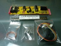
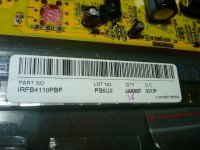
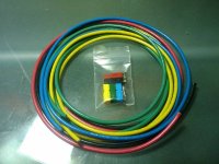
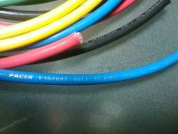
Instant Start 18 fet Infineon Boards are here...

sorry doc I never used the LED diagnostics I always got out the multimeter.
pads p1, p2, p3 are for LED's as well one for speed 1,one for speed 3 and one for when cruse control is active, I can't remember the order off the top of my head I have only just pined it down myself, this will not help you though I don't think.

Geoff
 
CamLight said:
liveforphysics said:
I agree. This resistor nonsense seems like the way to come up with control power voltage without spending more than $0.02.

My brain won't let me believe that there is not an elegant simple single IC bucking regulator that could take ~40-150vdc in, and output a steady 12v or whatever the circuit needs to see. It's not like we are looking for a lot of current on the control power.
How about the Texas Instrument's three-terminal adjustable linear regulator, the TL783?
Good to 125VDC input, 700mA output,and less than $2 at Digikey.
Just add a 1uF input cap and a 10uF output cap, 2 resistors, and you're done! :mrgreen:

John, i searched for that LM regulator and i found that it is not a switching type.. so the heat produced would be the same right?.. like a 7805 that we supply with 12V.. the heat produced(watt) is near: current x (Vin-Vout)..

For smaller circuit that may be a great solution but.. to me, the heat produced by this solution is near the same as with resistor right?

Doc
 
I've also noticed another difference between the clyte and infineon.. the 7805 on thecrystalyte is a to-92 little case regulator and the infineon have the to-220 case!.

infineon: 10uf 100V caps 7805 to-220

clyte: 100uF 100V caps 78L05 to-92.


the infineon seems to have a stronger 5V circuit...

Doc
 
the rational to use another regulator above the LM317T is because the need to keep the power resistor value at 600 ohm pulls the voltage regulator input so high it is outa spec and drags the 12V rails up with it. i know the infineon will run with the 5V rail at 6V and with the 12V rail at 19V.

idle current is only 53mA so the idle on a hot pack is the time when the input to the LM317T would be highest and the pack would likely be sagged down in use so the regulator would fall into the top of spec pretty fast when the pack was discharging. allowing the sag to bring the 12V rail down.
 
Doctorbass said:
John, i searched for that LM regulator and i found that it is not a switching type.. so the heat produced would be the same right?.. like a 7805 that we supply with 12V.. the heat produced(watt) is near: current x (Vin-Vout)..

For smaller circuit that may be a great solution but.. to me, the heat produced by this solution is near the same as with resistor right?

Doc
Hiya Doc,
Yes, you're right. There will be some heat. But, how much current do you need? I only recommended it because of its high voltage rating and extreme ease of use. But, if you're drawing too much current, it could get too hot. It is better than any resistor-only solution because a regulator's voltage will not change when the load current changes.
 
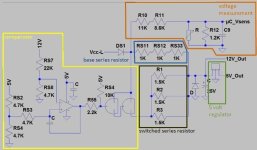
Hi guys, attached you can find the schematic of the voltage regulator part. Please, just have a look before talking about adding a switching voltage regulator.

Voltage_Reg.jpg
This solution is different to them I have seen before. The new solution is using two series resistors in parallel to get the voltage town to 12V. The 12V are needed for the gates of the fets. Than we have the 5V regulator. It is made in the same way as we have seen it before.
The input-to-12V regulator is not a poor linear regulator. It works like this:
The first series resistor, I called base series resistor, is always in use. The second one can be switched on and off by a comparator. This one I called switched series resistor.
The base series resistor has a higher resistance (3K) as the switched series resistor. So the base series resistor can’t transmit enough current to have 12V on the output side. The comparator detect that we have a voltage lower than 12V and switch the switched series resistor on. The switched series resistor (500R) is now transmitting more current until we achieve 12V on the output side. Than the comparator switch the switched series resistor of. To avoid swinging we have a smoothing capacitor on the 12V side and a hysteresis capacitor on the comparator.

The SMD 1Kohm resistors will work till 75V battery voltage. May be this is why the max regen voltage is also limited to 75V. I guess this solution can handle an input voltage range from 75V down to 45V without any changes. For higher or lower voltages we can just adaped the resistors!
regards SAM-Pilot
 
SAM-Pilot said:
Hi guys, attached you can find the schematic of the voltage regulator part. Please, just have a look before talking about adding a switching voltage regulator.


This solution is different to them I have seen before. The new solution is using two series resistors in parallel to get the voltage town to 12V. The 12V are needed for the gates of the fets. Than we have the 5V regulator. It is made in the same way as we have seen it before.
The input-to-12V regulator is not a poor linear regulator. It works like this:
The first series resistor, I called base series resistor, is always in use. The second one can be switched on and off by a comparator. This one I called switched series resistor.
The base series resistor has a higher resistance (3K) as the switched series resistor. So the base series resistor can’t transmit enough current to have 12V on the output side. The comparator detect that we have a voltage lower than 12V and switch the switched series resistor on. The switched series resistor (500R) is now transmitting more current until we achieve 12V on the output side. Than the comparator switch the switched series resistor of. To avoid swinging we have a smoothing capacitor on the 12V side and a hysteresis capacitor on the comparator.

The SMD 1Kohm resistors will work till 75V battery voltage. May be this is why the max regen voltage is also limited to 75V. I guess this solution can handle an input voltage range from 75V down to 45V without any changes. For higher or lower voltages we can just adaped the resistors!
regards SAM-Pilot

Thanks Sam, this is very usefull.. since now the controller STOPED working for an unknown reason :( ..

let me explain: It worked fine before i did two changes: first, i replaced the 3 parallel resistor 1.8K for some new 2.2K to ensure that does not overheat at 100V.. also i replaced the little 100uF 100V caps on the vccl close to the regulator for a 160V.

then i've put the pcb in the casing, added heatsink compound on the fets cooper bar and fixed the endcap..

after that i connected it to the bike and supplyed it with my lab power supply set to 5V for safe start...and watched the current on the lab power suply to ensure everything is ok....

but!... i was surprized to see that theLED that i connected on the 5V rail via a resistor ( as a power ON indicator) was already ON even though i had only 5V at power input!!.. then when i increased the voltage, the current increased as a linear relationship to the voltage.. just like if something would make a short circuit in the regulator circuit or like some kiloohm serie resistor could have been bypassed... .. than as i increase the voltage to something like 60V, it was drawing like 1A still in standby mode!.. no throttle.. just powered ON... :?

.. i shutted doen the power supply, opened the controller case, to investigate on the board.. than i powered it ON again and there was nothing.. the led was not ON and the only current increase that occured was when i tried to increase the voltage.. but goes back to zero current.. ( i guess the current draw was just the time to charge up the 1000uF capacitor ..)

I measured the voltage at the input of the to220 regulator and i have less than 4V.. and the output seems never reach more than 1V... that could explain why the led that i use as power induicator and connected on the 5V rail does not come ON....

So now.. do you have any suggestion?.. Your schematic is welcome cause it will certainly help me to investigate..

Doc
 
Sam, do you have any other part of the shcematic??

we would love to have any other schematic part.. or the entire schematic!

also.. looking on the schematic, i just wonder.. how can the comparator work if it is supplied by the 5V that it also need to compare! :|

Doc
 
You guys are doing a great Job.
I am glad that this thread is finally picking up.

Doc - If anything blows up just let me know. I appreciate this great investigative work you are doing so I think I will send you another Infineon kit as "parts board" in case you blow anything else up. I wish you were in the US so we wouldn't have to waste all this money on shipping! Go ahead and strip parts of the Crystalyte if you need them and you can replace them with the parts board I send you.


SAM-Pilot - Thanks for posting your 12V regulator schematic. P.M. your address to me so that I can send you a free controller kit for review. Your insight into the circuit is greatly appreciated. I look forward to further findings.


-methods
 
Do you have had 1A on Vcc-L (Logic) or for both, Vcc and Vcc-L? If you have had 1A on the Vcc-L you must have an error at or before the series resistors, otherwise they would limit the current anyway.
You have considered the polarity of the new capacitors, right?
:roll: May be you have blown the diode (DS1) which is in line to the 3 SMD and the power resistors (right under the 25V capacitor).
But: It the diode is blown, find the error before exchanging. Otherwise it will happen again… :?


Doctorbass said:
Sam, do you have any other part of the shcematic??
I have only created the schematic of the voltage regulators unit until now.

Doctorbass said:
also.. looking on the schematic, i just wonder.. how can the comparator work if it is supplied by the 5V that it also need to compare!
The 5V for the comparator are made by the linear voltage regulator. Some input voltage is always supplied by the “base series resistors“ (lower than 12V, but the comparator starts working at 2V).
 
SAM figured this much out by just investigating the pictures he collected.
Once he gets a board in his hands I think he will be able to help a lot more

-methods
 
With 42.4V input and switch ON,

I have the 41.7V out of DS1 diode and 4.0V at the output of the 3k serie resistor group wich seems a bit low.. so i guess that it may be the zener or the 7805 regulator that have something strange..
I have 916mV out of the 7805 regulator ( with the 4V input)... and i know that these regulator usually need at least 6-7v to have clean 5V output.. and i have low than that.. i'm pretty sure it's the zenner ( D0_1) that is a 1N4744 wich correspond to 15V zenner to liimit voltage at input of the regulator 7805..

But.. wait a minute.. I remember that last time when i connected that controller to my lab power supply, the capacitor inside was already cahrged from the previous time i used it.. and the psu was adjusted to zero V.. so maybe i guess that the crow bar circuit that force down the voltage of the output of the psu may have shorted the controller capacitor thru the VCC_L ?? that could have blown the zener? :?: :shock:

I test that right now :wink: !


5 min later..


ok.. the zenner is ok.. .. no change occur if i disconnect one leg of it.. i still have 4.0V instead of 15V

2 min later...

I also disconnected the 5V regulator.. and i have 5.00V output...

things make me think that t's on the 5V rail that i have something drawing too much current!..

.. hmmm.. things goes bad for me... my multimeter 9V batt is dead... let's take the second backup multimeter..

I'll repair that thing!!

Doc
 
Things goes worst guys... :( ......... :evil:

it seems that these infineon controller had more cause problems to me than any other controllers...

built two "discovered to be softstart" controller... got a similar crystalyte with... fake mosfets.....

then... the one i spent like 10 hours on it to built it perfect!!.. the lastest infineon imediate start controller is now blown...

guess that?!!!! :evil: .. it'S not the mosfet... IT'S THE fuc.....&?%&%(*% !!! uC !! .. that 116A ic that seems blown for unknown reason!!..

I know that cause after discovering that it draw too moch current on the 5V rail, it's because the UC is getting hot!!.. I decided to bypass the supply input of the 5V regulator after having lost 4 hour of investigation on the regulator voltage drop. then with an auxiliary 12V source direct on the rail cause the 5V that draw too much current make the 12V line to drop to 4V ...

so with a solid 5V on the rail, the current draw is 210mA and after sensing on the milivolt scale every trace to discover wich one cary abnormal current, i found that the Uc chip is hot.. not boiling.. but hot like 50 degree C...

:roll: :roll: :roll:

well... now..... should i take the one on the crystalyte and replace it.. taking a chance that it heat too caused by another unfound problem close to it on the pcb... or .. maybe it could work again...

I need a 150A controller alive and 100% fonctionnal.. I spent like 500$ of high end components on 4x 18 mosfet controllers.. and maybe 50hour of work on them.. .and I feel i lost my time... Rrrr!!

Maybe i should better have bought your Kelly controller Methods... :? :( ...


now.. 17 june is coming very soon... lol... i asked kelly compagny directly to have them as sponsor.. and .. they only offered me 10% discound... :roll: ...


welll.. this is a bit discouraging...

Maybe i should return working on the frame of the drag bike...


Doc that feel bad.... :(
 
That is the name of the game Doc.
I am sure this is not the first time you have been disappointed :)

If it makes you feel any better, each of the Infineons I have built have been great controllers.
Once you clear up your bugs you will be very happy.

I ran the 12V regulator in stock form for a week at 100V and had no problems...
I think this may be a classic case of changing too many things at once, know what I mean Doc?

If you have the skill to swap the chips then do so and I can provide a replacement board.
Before you do that though, please confirm that your modifications to the 12V system are sound.
I would personally just return the 12V regulator system to stock form - 1.8K load resistors - 3K inseries

Luke can share tips with you on how to swap the surface mount chip - it is really quite easy with a little practice.

-methods
 
if you have a heat gun, just carefully mask off the rest of the board near the ic you want to lift. Then flip the board upside down, and fix it in a vise so the parts that get warm on the other side of the board dont move around. Put the heat gun on high, get it hot, and blast the ic up close and as intensely as you can. In about 2-5 seconds it should drop right off the board just as neat as can be. Then let the board cool, flip it back over, clean up the trace pads with your iron, and you are ready to mount a new IC.

When you get the technique down, it only takes 5mins. But you might want to practice on some stuff you dont care about to refine your technique. masking the board is critical. Kapton tape and tin foil generally works pretty well.

Good luck! i have faith in your Doc Bass!

Best wishes,
-Luke
 
UPSIDE DOWN!
Oh... DUH! I get it now. :roll:
Every time I try to do it the board is right-side-up and the chip just slops around and gets hosed.

Upside down :wink:

I can see why Kapton with aluminum foil would probably be better than aluminum tape since the Kapton is less likely to leave behind a nasty mess. I dont know what Aluminum tape does when it gets to 400F but I bet it leaves residue.

Thanks Luke
-methods
 
Thanks for the trick Liveforphysics.. and thanks too Methods for your encouragements

I did not abandoned..

:wink: .. I have all equipment at job to remove this IC.. but i worri if i replace it with the one on the backup crystalyte and it blow too!!! :shock: so i would have zero working controlelr... I mean if it could be something that make it to blow.. a surounding component.. is it 5V supply this IC or 3.3V.. I mean it could be a little ic that take the 5V to the 3.3V or so... that blown and now is at 5V???

maybe that the problem below is the responsible.. I think that this ic may have received higher voltage than supposed to !!


I noticed something that may be responsible of all that mess.

the crystalyte board is not concern by that problem because the case is simply wider..

let me explain: (the controlelr pcb worked just fine BEFORE i install it into the case.....so....guess what... :| )

The slide where the board goes into the aluminum case is VERY close to the pcb traces... I mean I think the VCC may have shorted the 5V

because of this.. :shock:
 

Attachments

  • compilation.JPG
    120.8 KB · Views: 1,171
so the crystalyte 12V (15V) rail draw 30mA on the working crystalyte controller when i dirrect supply it with 14V

And draw 210mA on the infineon.. making the ic to dissipate 210-30=180mA x 14V = 2.52Watts... :!:

I guess it is blown or somethig around make it shorted on some legs...

Doc
 
Doc,

I had those days .. where i just want to give up ebikes because of the problem with reliablity .. and high currents.. i would just sleep on it and come back to it when your mind is clear to start again .. if it doesn't work .. call it a night!!

-steveo
 
Doc - The case should be 100% isolated.
If the +5V touches, this is not a problem.
If there is a problem then that means that Something else is also shorted to case :idea:

Very nice catch though Doc!
I have a bottle of conformal coating that I am using on the boards I am building up. I will put a spot on that 5V pad.

Good job Doc!
Keep your head up - and I think you may have found your problem. Isolate that case!!!

-methods
 
I put a couple of kits together for Lyen and SAM-Pilot.
Both of these guys have only made a handful of posts but they came into the community answering questions - instead of asking them :wink:
Thanks for the help guys. I hope you do something with these kits that will bring all of us closer to an affordable 10KW controller!
'
'
Fets_On_015.jpg

Fets_On_016.jpg

Fets_On_017.jpg

Fets_On_020.jpg

Fets_On_018.jpg

Fets_On_021.jpg

Fets_On_022.jpg

Fets_On_024.jpg

Fets_On_025.jpg
'
'

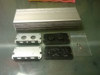
Base Kit with (18) 4110 Mosfets & USB programmer: ($ Not for sale yet )

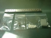
- Housing
- End caps
- End cap gaskets
- End cap fasteners (8 coarse)

- Heat sink
- Heat sink insulator strip
- Heat sink fasteners (5 fine)
- Mosfet fasteners (18 fine)
- Mosfet fastener insulators (18 plastic)

- Fully populated PCB board (no fets)
- Large 100V 1000uF caps
- Regulator resistors for 36V – 100V
- 16” Solder wick for building up traces

- (18) IRFB4110 mosfets included

- USB Programming cable w/header

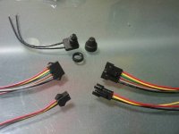
- Button switch with rubber cover

- Crystalyte 3 pin throttle pigtail
- Crystalyte 3 pin brake pigtail
- 6 pin CA pigtail
- 6 pin Hall pigtail

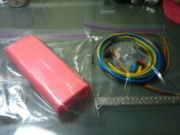
- 10 AWG Marine Grade tinned copper wire
- 24” Positive and negative leads (Red, Black)
- 48” Phase leads (Yellow, Green, Blue)

- 45A Anderson Connections for power and phase
- Red, Black, Yellow, Green, Blue

***********************************************************
I know that some of you are getting anxious for a kit and I keep putting you off....
I am sorry but I am still holding the kits back for a little longer.
I am just putting these two out because I think we can learn a lot from SAM-Pilot and Lyen.
Lyen will figure out the software and SAM-Pilot will help us to understand the hardware.
This will make the kits better for all of us!

Just look how many lessons doc has learned for us :mrgreen:
Gary is right behind him but he is dragging his feet :roll: Too much power for the old guy :D
**********************************************************

-methods
 
Hy Doc, don't give up! :!: :!: :!:

You are the technology leader here. 8) If you have the equipment at your job, just change the uC. You can test controller by supplying 14V to the input of the 7805. If you are using a current limit of 50mA on your lab power supply there should blow nothing, even if the problem is still there.
:arrow: I have made some comments on your compilation.JPG
 

Attachments

  • compilation.JPG
    126.6 KB · Views: 1,071
SAM- Pilot- You are a very very smart guy! It is great to have you on our forum! Thank you so much for helping us all to get this figured out. I'm going to paypal Methy to pay for the controller kit he sends you.


Doc- At least it's E-bike controllers and not race car engines. Try spending a hundred hours and $6,000usd everytime you want to try out a new race engine idea. Then imagine that engine failing in the first 15miles. E-bike controllers are a damn cheap way to get to experiment and work on tweaking a design for better performance.

Best Wishes,
-Luke
 
SAM-Pilot said:
Hy Doc, don't give up! :!: :!: :!:

You are the technology leader here. 8) If you have the equipment at your job, just change the uC. You can test controller by supplying 14V to the input of the 7805. If you are using a current limit of 50mA on your lab power supply there should blow nothing, even if the problem is still there.
:arrow: I have made some comments on your compilation.JPG

WTF were they thinking when they designed that?
The case absolutely should be isolated from everything.
I wonder if you can use some Kapton tape or something along the edges of the board?
I'm pretty sure the processor runs on 5v.
After assembling a controller, I always check continuity between the case and the power and phase wires to make sure all the FETs are isolated.
 
Good idea with folding a strip of Kapton tape over the edges of the board Fetcher.

Methy- I have a giant roll of 1.5cm width and a giant roll of 2cm width kapton tape. If you want, just say the word and I will mail them out to you.

Best Wishes,
-Luke
 
Back
Top