• Hello ES! We could use some help to get us past the finish line on building the new knowledgebase for the forum.
    Can you donate? Please see our fundraising page. Thank you!

Issues replacing battery and controller on Virtue Frontloader

chadon2

New here
Joined
May 3, 2026
Messages
6
Location
San Jose, CA
I bought a Virtue Frontloader to ride my dog around town and it was working well until a thief ripped off the battery/controller while the bike was locked on my driveway :( I'm not experienced with ebikes and new to this forum, but hoping I'd get guidance on how to replace the components.

I made one attempt that failed, I bought a 14Ahr LFP battery and controller that per my understanding would work with a 250W hub motor. Assuming I got that right (see attached), the challenge is figuring out the wiring as there were no connectors left after the thief slashed the existing wiring. Therefore I hooked up a couple of terminal block strips and lined up wires with the same color... Afterward connecting the battery nothing happened, no response from the hub motor. Then I switched a pinkish wire to a more redish wire running to the display, then after connecting the battery the display made a popping noise and a puff of black smoke came out; assume that display is finished. Lastly, I read that the display can be bypassed by shorting the red display wire from the controller to the blue one; this also did not have any impact on the hub motor. Added some pictures to help show the situation.

Advise on what to do next, or even what I should not have done, is welcome. Thank you!
 

Attachments

  • 2026-05-03 Wiring failure.pdf
    333.5 KB · Views: 9
You have a KT controller, and it only works with KT displays, Before you snipped off the connectors, I hope you had the controller wires organized or saved the ends, I've installed a lot of KT controllers. It's all I will use on my hub motor projects.

I recall the pink wire was used to switch power to the 5 pin display connector/ The controller should be OK them. As for displays. I like the mono KT LCD3 display because it's easier to see than the smaller color LCD11 and LCD9C. I've never used an LCD8.

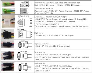
page1.jpg
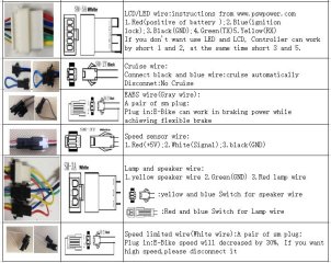
page2.jpg

KT units usually ship with a pre-wired jumper plug om the 5 pin display connector to run w/o a display. Until you get a KT display,. you can put the old connector back on, and insert the jumper. Or tie the blue/red together. They suggest black/yellow too. Not needed.

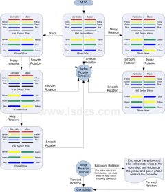
Then verify the motor connectors. I have been lucky. Connected over a dozen KT units to motors and it always worked matching the colors on the three thick phase wires and the six small sensor wires. If not, there is a simple method to logically trial and error the various color combinations so you only have to do about 5 iterations to find the right match without having to do all 35 logical possibilities. More about that later.

Next thing to try is the red-blue jumper on the display wires to bypass the display. This turns on the control logic inside the controller and you will see 5 volts appear on red/black wires from the hall sensor, and also the power wires of the throttle, speed sensor and and the pedal sensor. Once you have power, you can try running the motor.

To run the motor, I suggest a throttle. The pedal assist input can be problematic. All you need on the throttle connector is 2-4 V power across the blue and black wires. Best to use a throttle, but you can use a resistor bridge, or a diode between the 5V power and the input. Touching 5V to the input won't work.

Here's the flow chart for sequencing the motor connections. It does work.

GsugRE9.jpg
 
I received a new display recommended by Docw009, KT-LCD3 V3.0 4HS 72V, and did some initial setup with the previous controller I bought KT36/48VPR-ffF10L. I haven't powered anything up yet as I have a few uncertainties around making the correct connections and would rather not repeat the destruction of equipment (last one I torched). Attached photos and notes to hopefully make the situation more clear.

Unfortunately I didn't take pictures of the new controller connectors before I cut them, and it didn't come with documentation. Also, I have no record of the original stolen controller. So left with a bit of a puzzle consisting of wire bundles and wire colors.

I highlighted a couple questions in red text boxes regarding the Hall sensor wires and the PAS connection (maybe lacking throttle?). Input and suggestions are very welcome. I have a multimeter if that will help perform step-wise checks.

Thank you
 

Attachments

  • 2026-05-16 Wiring New Display.pdf
    793.7 KB · Views: 2
Well I didn't get any response, but I have some time over the three day weekend so I'll give it a go.

I feel more optimistic about not burning something up as both the new display and controller are KT, and there are wire colors that match between them. Still unsure why I have only have a total of x6 wires going to the hub motor, seems I am missing the Hall senor wires?

Any advice before I power it on is appreciated, thank you.
 
Well I didn't get any response, but I have some time over the three day weekend so I'll give it a go.

I feel more optimistic about not burning something up as both the new display and controller are KT, and there are wire colors that match between them. Still unsure why I have only have a total of x6 wires going to the hub motor, seems I am missing the Hall senor wires?

Any advice before I power it on is appreciated, thank you.
In order to have hall sensors you need at least 8 wires to the motor.
3x phase wires
5v +
Grnd
3 hall sensor wires
(And the 6th in the plug is usually white for a speed sensor or a temp sensor)
 
Thank you, so given the wire bundle going to the hub motor only has the x3 phase thicker wires, and x3 (red +5, black GND, white speed?), I suspect I have system without Hall Sensors. See photos from response 5/3.
Guess the question is whether or not the controller I bought works without Hall Sensors.

AI's understanding: The controller estimates the motor's position by reading the electrical currents (back-EMF) generated by the spinning coils. While this setup is more reliable (since sensors can fail from heat or moisture), you may experience slight stuttering or rough acceleration when starting from a complete stop.
 
Confirmed that the display works with the controller and battery I have, thank you for the display suggestion @docw009
However, still unable to make the hub motor run. Assuming I don't need Hall Sensors(?), then remaining question is the PAS/Throttle I think.
Currently I have x3 wires to the PAS on the bike side (blue, red, black), connected to the controller 'bundle' (white, red, black). When I turn the pedals nothing happens, so thinking these wires are for throttle instead of PAS? Any recommendations on a throttle switch to try or other workaround?

Note, I am still unable to find a pin out documentation for KT36/48VPR-ffF10).
 
Back
Top