Jbd bms SP17S005 smart BMS issues

cloudy

10 W
Joined
Nov 24, 2020
Messages
73
Location
Australia
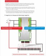
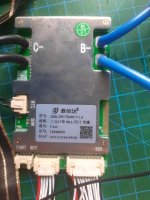
I've bought a JBD smart bms recently and have rigged a primitive16s1p test board with old cells to test the functions. Including abnormal states like over temperature and unbalanced cells. I Soldered all the balance wires onto the cell holders and have wired up b- according to schematic. Balancing and charging worked fine, and temperature protection did interrupt charging when above threshold.
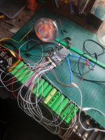
1000005999.jpg

Can anyone please help with any of the following issues:

1. The bms remains powered on as long as the balance wires are connected. A blue light flashes and the battery is slowly discharged by the bms. What is the best way to turn off this bms with switches or software?

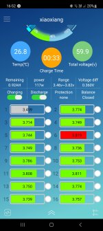
2. Discharge switch in the app did work and turn on and off the light I connected, but power consumption did not register for discharge, it shows 0w with the light on. I am charging and dishcharging through C- and the main battery positive, B- is on the battery negative. Only charging power appears on the app. How do I make discharge power show up, or what have I done wrong?

3. I disconnected B- and upon reconnecting it did not restore normal function. How do I reset the bms after powering off? Unplugging balance wires appears to reset it but this is cumbersome.

I plan to use this bms in a 16s9p e bike pack I'm building.

Thanks!
20230930_172754.jpgScreenshot_20230930_144134_Gallery.jpgScreenshot_20230930_165220_xiaoxiang.jpgScreenshot_20230930_165208_xiaoxiang.jpg
 
1. The bms remains powered on as long as the balance wires are connected. A blue light flashes and the battery is slowly discharged by the bms. What is the best way to turn off this bms with switches or software?

If it has pads or connectors for a physical switch you can configure in the app for disabling the BMS (powering it down including bluetooth), that is the best option. I see pads for an SW that is probably "switch", probably used to turn it on and off, but it isn't populated with a connector.

That could just be saving the money on the connector, and the switch would still work if soldered to those pads, but it could mean the function is factory-disabled on this model or version, or that other parts required to connect from the connector to the MCU aren't populated either.

If it has no physical switch options, you'd have to turn it on and off in the app if it has a way to do that, but obviously it has to keep the BT alive and powered on, as well as it's MCU, using up power for those, in order to be seen by the app so the app can send and the BMS can receive the turn-on command.


2. Discharge switch in the app did work and turn on and off the light I connected, but power consumption did not register for discharge, it shows 0w with the light on. I am charging and dishcharging through C- and the main battery positive, B- is on the battery negative. Only charging power appears on the app. How do I make discharge power show up, or what have I done wrong?
On most BMS, C- is usually just for charging. P- is usually for discharging. In those systems, sometimes it can only monitor current in one direction on each port, so it wouldn't show you discharge current on the charge port.

For this one that's intended to have it all routed thru C-, I don't know why it wouldn't show discharge current too, unless it isn't actually discharging, but I assume you've already verified the amount of current that's flowing out with a separate meter?


3. I disconnected B- and upon reconnecting it did not restore normal function. How do I reset the bms after powering off? Unplugging balance wires appears to reset it but this is cumbersome.
Does the app have a reset function? If not, there may be pads or a connector for a reset button.

On some BMS designs, unplugging balance wires has a risk of damaging the sense circuitry, becuase not all connections may disconnect or reconnect in the order from most negative to most positive, and may place voltages across components in ways they weren't designed for. If it's well-designed, they'll have installed protections against that but that isn't typical.

Same thing for disconnecting other pack-to-BMS wiring--if it isn't specifically designed to handle this, in the order that it's done, and states in it's documentation that this is how it should be done, it may not gracefully handle the situation or it may become electrically damaged.

It doesn't usually break anything to disconnect things, but it can, and has on some BMSs. (usually the "dumb" designs rather than the better smartbmses, but without knowing the electrical design and analyzing it, or having documentation stating it's ok to do, it's safer to assume it can't handle anything other than disconnecting in the exact reverse order that it's documentation requires connection order to be in).
 
Last edited:
thanks AW!

There are 4 pads in the box marked "SW" do I just short out two of the larger ones to turn BMS off? Bit reluctant as I don't want to ruin anything by shorting it out.

I did not measure load current but there is at least 20W being consumed by the glowing light bulb in the first photo. With the light bulb ON, power shows as 0W in BMS. Toggling discharge on/off in the App does turn on/off the light but there is no change in Power display. I'm not sure how any of the discharge protections will work if it is not registering any discharge current. This is still a mystery to me.

Hopefully I haven't broken my BMS already by disconnecting balance wires! There seems to be a lack of documentation for this BMS, but I may have missed something in my search.
 
thanks AW!

There are 4 pads in the box marked "SW" do I just short out two of the larger ones to turn BMS off? Bit reluctant as I don't want to ruin anything by shorting it out.

If you look at the connector next to it, you'll see the ones closer to the edge of the board just secure the connector in place. The other two are the signal pads. This should also be true of the unpopulated connector.

But you should check the BMS documentation for what this SW connector would do and how to enable it, etc.; if you have no documentation you should be able to get it from JBD. It will probably be in Chinese, but there are online translation tools that may help enough to figure it out.
 
Double check the app function settings. I've found the toggles are sometimes backwards to the actual setting, or the default settings are not consistently configured with these BMS.
I've also had at least one of these where I had to switch to another app, AXE BMS in order to use it. Hope that helps.

Cheers
 
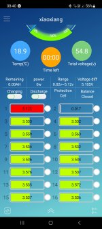
I while unplugging the BMS from the test setup the blue magic smoke came out of the BMS where the balance leads plug in. Now when I plug it in, cell group 1 reads incorrectly as 5V and group 2 shows 0V, so I fear I have fried this BMS. As AW mentioned these things seem pretty sensitive to the order they are connected, I'm not 100% sure I even did anything out of order or what caused it to fry. I doubt Ali will provide any refund so it's looking like I'll need to buy another... Question is if that will be JBD again or something different.
 
Why do you choose QUCC cowardlyduck, and is there a way to turn on/off via software or a physical switch? What is quiescent current usage?

Can you please share a link for what you mean? I'm getting many results searching for QUCC smart bms for 16s
 
Yes, QUCC are based on JBD I believe.
I haven't tried all the BMS, but out of the 4-5 different brands I have tried, I've found QUCC to be the most reliable.
From my experience the physical switch on these does work if used. I usually don't use it though as the discharge rate it pretty slow.

I recently bought a bunch of these and they seem to be working well:

I should also add, I am not sponsored by them at all....but maybe I should reach out given the number of their BMS I buy!

Cheers
 
Ok cheers, for that. I'm also considering Heltec BMS, which look quite different and were recommendedby a friend. Has anyone tried those, and are they also JBD based?

I've been pretty unsatisfied with JBD. I'm pretty certain open circuit on b- or one of the balance leads fried it, and the discharge current measurement was buggy while it was working also. They don't seem very robust. Does your discharge measurement work on QUCC cowardlyduck?
 
Does your discharge measurement work on QUCC cowardlyduck?
Yes.

I'm pretty sure most of the cheaper 'smart' bluetooth BMS use JBD based boards, including Heltec.
One that may not is Daly, as they cost more and my experience with their 'smart' BMS has been terrible and I could not use it in the end.

It's a bit like dash cams were (still are to a degree) for a long time. If you look into it you will find they almost all use the same set of 3 cmos chips and pre-made IC's from the cheapest to the most expensive, they all use the same sensor. The only difference is marketing and add-on features.

For the most part, different BMS manufacturers will add differing components onto a JBD board, throw some marketing and a logo on it's heat-sink, call it a day, leaving the testing to the end user and make a profit. It could be that the additions to yours are what caused it to fail, but I'm confident that it's not the underlying JBD based board given the many dozens I've used without problems.

Cheers
 
Ended up getting the same JBD bms, this time with QUCC printed on the heat sink. It works fine for now. I was careful to connect B- before balance leads, and tested all the soldering of balance leads prior to plugging in.

I have noticed the Bluetooth connection is fairly buggy, and seems to cut out when the battery is charging. It's unfortunate that configuring the max voltage is so slow, otherwise I would use this setting to limit state of charge and allow custom charging. Also not having a charging port on the bms means any max voltage setting will affect regen also.
 
Back
Top