BMS bad... or something else?

pistolpete1776

100 µW
Joined
Sep 22, 2023
Messages
8
Location
Philadelphia
Hi - newbie here to the forum. I did search my issue and definitely got smarter, but still need some guidance.

My GF has a Blix ebike and she didn't charge the battery at all this past winter. The battery does have an on/off switch and it was left off (which I guess disconnects the BMS so it doesn't drain). The battery was kept inside, disconnected from the bike. The battery also has an LED charge indicator.

The battery is a 48v 14ah 13s4P with Samsung 18650 cells.

The problem is that the battery is completely non-responsive. At the power output terminals I get 0.9v. Nothing on the LED charge indictor.

Opening the battery case, I inspected everything. All wires well connected. No sign of burns or other heat issues.

I reset the BMS using the common online instructions - disconnect balancing harness from BMS, plug in charger, reconnect harness. No help. Is there another way to reset the BMS?

I tested the battery pack and each cell. Across the entire battery pack I get 54.1v. I get the same 54.1v at the charging terminal. I tested each of the 13 cells, both on the pack and at the balance wire harness, and I get 4.2v for most of them and 4.1 for a few. With the balance wire harness disconnected from the BMS, I get 33.1v at the power output terminals. When I reconnect the harness it goes back to 0.9v.

So I'm thinking the battery pack is good and the BMS is bad - does that sound right? Or is there something else I should be trying to revive this seemingly good battery?

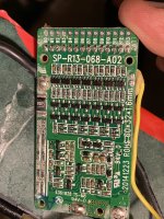
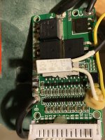
If replacing the BMS, what amperage should I use? The motor is 500w and I suspect the current BMS is 15a. Attached are pics of the current BMS. It looks like they piggybacked the on/off switch on the thermal protection lead.

Thanks for the help!
 

Attachments

  • IMG_0846.jpeg
    IMG_0846.jpeg
    940.5 KB · Views: 8
  • IMG_0848.jpeg
    IMG_0848.jpeg
    715.1 KB · Views: 8
Last edited:
I tested the battery pack and each cell. Across the entire battery pack I get 54.1v. I get the same 54.1v at the charging terminal. I tested each of the 13 cells, both on the pack and at the balance wire harness, and I get 4.2v for most of them and 4.1 for a few. With the balance wire harness disconnected from the BMS, I get 33.1v at the power output terminals. When I reconnect the harness it goes back to 0.9v.

Sounds like the BMS is working normally.

A difference in voltage of that magnitude between cell groups is pretty significant, usually indicating a significant difference in cell properties (capacity, internal resistance, etc), and at least some BMS will disable charge or discharge because of it. This is normal, and done to prevent potential cell damage that could lead to a fire.

It's unlikely that would be an issue in this case, since the cells are not anywhere near overdischarged or overcharged, but the difference is there and if it's because of the cells themselves, the imbalance may return during usage.

If it's because those lower cells are the ones used to power the BMS itself (the most negative ones, closer to the B- wire), then it's not a cell problem, just that the BMS drained some of the cells while not draining others.

If you feel comfortable with the idea, you can try either draining down the high cells or charging up the low cells just a tiny bit to put them closer to the same voltage.

Note that it is easy to slip and make an accidental short between groups which can damage things or even start a fire, so be very careful when doing either of these things.

If you'd like to try, we can give specific instructions depending on your available tools/etc and your skillset and comfort level.

Thank you for the response. Yes, I'd be willing to try. I have good access to the sides of the pack so would likely charge/discharge at the balancing lead attachment points. My multimeter is only good to 0.x - should I get one that measures to 0.xx? Any instructions/advice would be appreciated.
 
Which meter do you have? Even my cheap (free from harbor freight with coupons years ago) can do two decimal places, though I wouldn't vouch for their accuracy :lol: they're still good for relative measurements like this sort of thing.

If it is autoranging try setting the range to manual to the 20VDC level.

Being sure that there really is a whole tenth of a volt or more difference before trying to manually balance cells could save a bit of trouble. :)

Also, verify that the battery in the meter is good, since most meters read high when their internal battery is low.

Do you happen to have old salvageable electronics stuff laying around that can be used for parts? If so, there may be parts that can be used for some of the balancing work.
 
Last edited:
I have a Milwaukee meter that has autosensing voltage (AC/DC). I'll pick up a cheap meter that is more sensitive and has manual range. I do have wire, connectors, soldering gun, etc. I'm fairly handy. Have done auto electrical work.
 
Maybe, if you're willing to solder on the proper connector to each set of six parallel groups of cells to then plug into the balance port of the charger. You can buy lead sets that plug into the balance port with alligator clips, but there is the risk teh clips will slip off (potentially shorting something) or will have too high a resistance of a connection, causing an imbalance instead of fixing it. (or you can use the main port and set it to 1S mode if it has that option, and do just one cell group at a time, less risk of clip slippage as there are only two instead of seven)

Before doing that I'd just check that the voltages are actually off by as much as your meter has suggested. :)
 
But why do you think the battery has any balance problem if all cells are more or less same voltage and seem to be fully charged? The battery is fine and BMS shouldn't cut off the power imho.
 
But why do you think the battery has any balance problem if all cells are more or less same voltage and seem to be fully charged? The battery is fine and BMS shouldn't cut off the power imho.

I already stated why, if you read the previous posts. :)
 
I have to disagree with amberwolf about a .10 volt difference in group voltages shutting down a BMS. I've seen deltas as high as 3/4 volt and the batteries either still charged, or still discharged. As long as the lowest group is above the minimum, usually 2.9 -3.0 volt, my batteries still worked. Maybe you missed one of the 13 groups, and as luck would have it, that's the one that's off.

It's possible that one of the balance wires got loose at the pack, I suggest reading the voltages at the open balance connector. Since voltmeter probes won't fit, I stick pins in the connector to access the voltages. If this checks out with everything at 4.0-4.2V, then plug the BMS back in, put the black end of the meter on the B- and walk your red probe from B1 to B12, making sure you see the voltage increase by 4 volts on every step.

Also check you have a good battery in the voltmeter, because they read high when the battery is low.
 
I have to disagree with amberwolf about a .10 volt difference in group voltages shutting down a BMS. I've seen deltas as high as 3/4 volt and the batteries either still charged, or still discharged.
It depends on the BMS design and setup (if any). That's why I said that "at least some BMS" would do this.

There *are* BMSes that do shutdown on that amount of difference--there have been battery repair threads where this was found if you have time to find them.

Some of the programmable ones have a setting for the allowable difference. If they're not programmable there won't be a user-alterable setting, but it would probably be factory set to the same default as the programmable ones, which seems to be 0.1v for the ones posted so far.

What this BMS does, we don't know yet, until the cells are measured with something that can tell us what the *actual* difference from highest voltage cell to lowest voltage cell is, and if it is >0.1v then rebalancing them and seeing if that enables the output. ;)
 
Hello all - thanks for all the help. So I have new meter with x.xx accuracy with brand new batteries. I took all the readings at the balance connector while it was disconnected from the BMS. All cells read 4.18 or 4.17 except one, which was 4.16. I also did what @docw009 recommended and took the readings (again at the balance connector) walking my probe from B1-B12. Each step was ~4.2 and the final was 54.2v.

I also took readings on the BMS, with the balance connector still disconnected. With the battery switch off, I got 54.2v at B-, 54.2v at C-, and 0.07v at P-. I also got 0.07v at the discharge port (which makes sense - same as P-). With the battery switch on, I got the same readings except at P- and at the discharge port I got 49.7v.

Last clue... There is an LED charge indicator that is wired to the + and - discharge ports. With the battery switched on, and the balance connector still disconnected, I get 49.7v at the discharge port (like I said above). But when I press and hold the button on the LED charge indicator, all of the LEDs (one red, the rest green) give a very quick and faint blink and then go dark. Could there possibly be something wrong with the LED indicator? Should I try disconnecting that from the discharge port terminals?

What next steps would you recommend? Thank you again for the help diagnosing this one!
 
Last edited:
-All the cell groups check out.
-The voltages check out on the BMS.
I do not feel you have any cell voltage issues here.

Here's the spec sheet for the TB02-BB8D thermal switch, It's normally open and closes when hot. Maybe it's failed and closed. Suggest you unsolder. I believe you think it is in parallel with the OB/OFF switch, but that means the switch is open to start the battery. Oh well, take off the thermal switch and see what happens. Maybe there's another solder pad under the glob of glue,.
 
Here's the spec sheet for the TB02-BB8D thermal switch, It's normally open and closes when hot. Maybe it's failed and closed. Suggest you unsolder. I believe you think it is in parallel with the OB/OFF switch, but that means the switch is open to start the battery.
I'm pretty sure the on/off switch is wired in series with the thermal switch. The switch has two yellow wires. One is soldered to the board adjacent to the white lead from the thermal switch (shown in photo). The other is connected to the second white lead on the thermal switch with black heat shrink tubing (also shown in same photo). So the thermal switch must be closed by default for the on/off switch to work, right, since "off" setting would open the circuit? When switched "on", then the circuit is closed unless the thermal switch opens the circuit if too hot (at 75C)? Just thinking this through before I unsolder. Thanks!
IMG_0848.jpeg
 
Last edited:
Update... I was able to find a new BMS on Amazon with the same balance connector as the OEM Blix one. However, it is only 15A and didn't have on/off switch support. Soldered the B-, P-, and C- leads and presto... 54.2v at the discharge port. So it was a bad BMS.

Thank you @amberwolf and @docw009 for the troubleshooting support!

I have ordered a similar sized 30A BMS with one/off switch support from AliExpress and will install that once it arrives. It has a different balance connector so I've have to solder on those leads to the pack.
 
Last edited:
Good to know! So without balance, the BMS is really just monitoring, but actively keeping cells in balance?
If you mean *not* keeping cells in balance, then yes. ;)

FWIW, if a pack is correctly built of well-matched cells (meaning *identical* characteristics: internal resistance, capacity, etc) and used well-within it's capabilities (not charged to full and not discharged to empty, and not used near their current limits), it will not need balancing until the cells have aged enough to become different. If it's used gently enough that can be a long time (years) if the cells are good quality.

Any pack that requires balancing already has cells that are different from each other, and making the pack perform worse than it would if they were all matched. The more balancing it requires, the greater the performance difference from ideal, and the less usable capacity you get from it as well.
 
That's true, a good battery will not need balancing for a long time, but inevitably such time will come with age. So i too think you dont really need the balancing BMS if you can install a connector for external balancer (also useful for monitoring the voltages). When the battery gets old the voltages need to be checked more often and corrected, this way you can get some more use cycles from the battery.
 
That's what I do with my EIG pack on the SB Cruiser--no BMS, but a conservative charge and discharge and current limit; they are large (well, medium these days) ex-EV cells with very good matching of characteristics from the manufacturer, so they don't drift in SoC and don't need balancing (over a decade old now). They *are* showing their age in greater voltage sag than before, but they all sag the same way at the same time, so at least balancing isn't an issue. :)
 
Back
Top