Bikeronin
New here
Hey everyone. I’m fairly new to this and I’m using this issue as a learning opportunity.
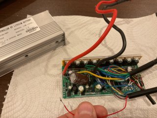
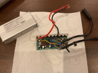
I have a JN controller that I received from Amazon as a secondhand. During installation, the Juliet connector got stuck, and when I pulled it out, the red wire was torn out of the controller. From what I understand, this red wire should be the 5 V supply for the display / logic, but I’m struggling to identify exactly where it should be reconnected.
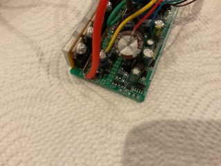
I initially assumed it would go to a pad marked with a “+”, but measuring there with a multimeter shows no 5 V present. I also noticed a small piece of wire residue near the VB+ (48 V battery input) area, which confused me — it obviously wouldn’t make sense for the controller to send battery voltage directly to the display.
I’ve spent a couple of days probing the board with a multimeter and testing different points, but I can’t find a clear 5 V output anywhere near the front of the board. Based on how the wire tore out, it feels like it originally connected towards the back of the PCB, not the main power section.
Where does the Juliet red (5 V) wire typically connect on JN-style controllers?
Any guidance would be hugely appreciated
Thanks in advance.
I have a JN controller that I received from Amazon as a secondhand. During installation, the Juliet connector got stuck, and when I pulled it out, the red wire was torn out of the controller. From what I understand, this red wire should be the 5 V supply for the display / logic, but I’m struggling to identify exactly where it should be reconnected.
I initially assumed it would go to a pad marked with a “+”, but measuring there with a multimeter shows no 5 V present. I also noticed a small piece of wire residue near the VB+ (48 V battery input) area, which confused me — it obviously wouldn’t make sense for the controller to send battery voltage directly to the display.
I’ve spent a couple of days probing the board with a multimeter and testing different points, but I can’t find a clear 5 V output anywhere near the front of the board. Based on how the wire tore out, it feels like it originally connected towards the back of the PCB, not the main power section.
Where does the Juliet red (5 V) wire typically connect on JN-style controllers?
Any guidance would be hugely appreciated
Thanks in advance.