Joey's Ebike #2

Joey

100 W
Joined
Jan 3, 2008
Messages
174
Location
Albuquerque, New Mexico USA
This started out as a simple project but has turned into quite a saga. I have decided to document the experience as well as some lessons learned.

My original goal was to build an e-bike starting with (1) a steel-framed hardtail with a decent front suspension, (2) a BMC rear hub motor from EVTECH, and (3) a 36V Headway LiFEPO battery pack from ebikes.ca. I also purchased a stock EVTECH 20A 36V controller and half-twist throttle, but planned to transition to a beefier controller as additional funds became available. As time progressed, the only items that remained from original plan were the bike and hub motor.

The bike I chose is a steel frame Giant Boulder which comes with a 21-speed trigger shifters and v-brakes. I upgraded the front fork to a RockShox Dart 2 and a mechanical disc brake.

I waited a bit too long to order the battery pack (I was saving up funds) so that when I finally placed the order, the only LiFEPO packs left in stock were the dredges. After waiting several weeks, and hearing non-commital statements about continued QC testing, I finally cancelled the order.

I wanted to utilize a battery system with either a proven track record and/or a decent warranty. My first e-bike utilized a eZee hub kit with 36V Li-Mn battery. I has worked very reliably for 900+ miles, but I was beginning to observe a noticeable loss of capacity after 4 months of use on that battery, and it's voltage was sagging significantly toward the end of my daily commute. If I was to stick with a 36V battery I wanted it to be LiFEPO. I was willing to tolerate noticeable voltage sag If I started with a higher voltage, e.g. 48V.

I eventually purchased 8 Milwaukee V28 Li-Mn batteries and four 1-hour chargers from toolup.com. I also purchased a 24-72V 35A Crystalyte analog controller, half-twist throttle, and Cycle Analyst from ebikes.ca. I then checked out jondoh's "milwaukee v28 cable how to video" and purchased eight of the connectors that he recommended and began assembly of Joey's ebike #2. Although I had eight batteries at my disposal, I was only able to fit six of them with connectors in my rear trunk bag.
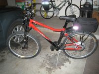
GiantEbikeV1.jpg

I apologize for the bright reflections in the photo. My camera flash bounced off the reflective stripe on the trunk bag and the pannier on my wife's bicycle in the background.


saga to be continued...

-- Joey
 
In order to make the hub motor compatible with the Crystalyte controller, I replaced the stock phase-wire connector with 30A Anderson power-poles and the hall signal connector with a round 5-pin from ebikes.ca. I shortened the hub motor wires considerably in the process. The length of the shortened wires was no more than 12 inches from the exit point on the axle to the end of the new connectors.

I took a short test ride in the evening and everything checked out ok. I put the batteries on charge afterwards. I biked into work the following morning, a distance 7.7 miles, mostly downhill. On my return home from work, the bike went about 50 feet on modest power and then everything went dead. I cycled power and CA showed only 43 volts and there was no go power. CA then dimmed and began to show some random characters on its screen. I kept things off thereafter and pedaled home.

After recharging the batteries, I did some simple experiments to try to locate the problem. The problem did not recur during a relatively short bike ride. I rode ebike #1 into the work the next day and puzzled over the problem. That night, I took e-bike #2 out for an extended ride at full throttle. After a 12 mile loop I was back near home. I then repeatedly climbed a steep hill near my house in an attempt to get the battery BMS to trip. Something died but it wasn't the batteries. The CA still showed decent voltage but the motor wasn't running.

When I got home, I turned the bike upside down and rotated the rear wheel by hand. I noticed that there was considerable "magnetic drag" which indicated to me that there was a short somewhere in the phase wiring. The back EMF produced by the motor was driving a dead short. I perceived that there was a BMC hub motor rewiring task in my near future.

I was apprehensive and timid about taking the hub motor apart. I saw some screws around the hub, but didn't know if the hub needed to be separated from the wheel or whether the sprocket assembly had to be taken off first. I asked around on this site and eventually got the answers I needed. It turned out to be relatively simple. The hub stays on the wheel and the sprocket assembly stays on the motor shaft:

(1) The first step is the most intimidating: Cut off the connectors from the wire bundle coming out of the motor. This needs to be done since the
axle and wire bundle will be pulled through the motor housing. Also remove the large nut and washers from the axle.

(2) Remove the 9 screws on the sprocket side of the motor

(3) Gently pry under the lip of the plate that has the screw holes. It is on the sprocket side of the motor.
Be careful not to bend the plate. I used a screw driver. I then slid in a second screw driver and
worked it around toward the opposite side of the plate.

(4) Lift the axle, motor, plate, and sprocket set as one complete assembly out of the motor housing. The motor housing will remain
attached to the spokes and wheel. Set the motor housing and wheel assembly aside.

BMC_Housing_With_Rim.jpg

(5) The sprocket assembly and plate can now be separated from the motor and axle. Mine pulled apart with very little effort.

hub_motor_separation.jpg

(6) Write down or take a picture and note the location, ordering, and colors of the three phase wires (the thick wires), and the five hall sensor wires (the tightly grouped, thin wires)


If you find that the ends of the wires are covered by potting material like mine was, you're in for some extra work.

the saga continues...


--- Joey
 
Jonathan had a similar burn out problem with his bmc. what gauge wires are on your bmc?
 
Hi jondoh,

I don't know for sure what the gauge of the stock phase wires was but I would estimate that they were 18 gauge. The wire insulation wasn't tolerant of high temperature either. I replaced the phase wires with 14 gauge stranded PTFE (teflon) insulated wire and have had absolutely no problems since. I used 24 gauge stranded PTFE insulated wire for the hall wires. I don't know if I could have fit 22 gauge, I didn't try it. I purchased the wire from Powerwerx. They had all the colors and gauges that I wanted.

-- Joey
 
There were two types of potting material covering the connections in my hub motor. A tan-colored, soft, waxy material covered the hall wire solder connections and a dark brown brittle material covered the three phase wire connections. After cutting the phase wires half way between the solder connections and the axle, I was able to remove the brittle potting material by crunching it a bit at a time with a pair of pliers. I covered the top surface of the motor windings with electrical tape to keep the loose bits from falling inbetween the windings. I first tried to use my soldering iron to melt the waxy potting material. It stunk so much (I was indoors) that I gave up and just scraped away at it with an Xacto knife.

I replaced the phase wires with 14 gauge stranded PTFE-insulated wire and the hall wires with 24 gauge wire of the same type. I soldered them in place, and covered the connections with RTV. Here is a photo of the connections before the RTV was applied.

BMC_new_wiring.jpg

I then closed up the motor, attached 30A Anderson powerpole connectors to the phase wires and a circular mini-connector to the hall wires, and mounted it on my bike for testing purposes. When I connected up the controller, battery, and throttle, I found a problem. The motor would run if I manually rotated the wheel slightly before applying throttle, but it would not move from a complete standstill. It also stuttered a bit at high speed. This led me to believe that something was wrong with a hall sensor or the hall sensor wiring. The lesson here is to check the wiring before reassembling the motor. I needed simple a way to test the hall sensors and wiring.

I found the following schematic by fechter on the E-S site. I then built a hall sensor tester from the schematic.

Fechters_Hall_Sensor_Tester.jpg


I unsoldered the round hall-wire connector from the loose end of the cable and connected the clip leads from the hall sensor tester to the hall wires. I then rotated the motor slowly and watched the LEDs blink. The two outer LEDs blinked with the rotation. The center LED (connected to the green hall wire) did not light at all. This told me that either the green hall wire was not connected properly or one of the hall sensors was bad. I took the motor apart a second time and followed the circuit board trace from the green hall wire to the middle hall sensor on the board. The middle hall sensor leads were covered with the same tan-colored waxy material as the hall wires solder connections. I was also now covered with a new layer of RTV.

It turns out that I had accidently loosened a hall connection when I scraped the material just above the hall wire solder junctions and got a bit too close to the hall sensor. It looked like it hadn't been completely soldered at the factory and the hall lead had simply detached from the conducting edge of the circuit board hole. I scraped off all the RTV, added some solder to the connection and re-tested the hall wiring with the tester. Now all three LEDs blinked as I rotated the motor. I then re-sealed the connections with RTV, waited for it to cure a couple of hours, and then closed up the motor. I mounted it back on the bike, connected up the controller, battery and throttle, and it ran like a champ.

Big lesson learned: Check continuity on the phase wires and check hall sensors and wiring before adding potting material and closing up the motor.

-- Joey

the saga continues
 
After putting some miles on my e-bike with the 2s3p Milwaukee 28V Li-Mn packs, I decided that I could use the added capacity of the pair of unused Milwaukee packs that I had already purchased. I was also rotating use of the 8 packs six at a time and it was getting tedious. I looked for the longest rear trunk bag I could find that still looked like it belonged on a bicycle. I found the following item on the web. It was called variously a Solar Trunk Bag or 'Nomad' Bicyle Trunk Bag on different sites.

Solar_Trunk_Bag.jpg

It was almost long enough to hold 8 Milwaukee battery packs with connectors but not quite. My solution was to modify the connectors by slicing them with an Xacto hand saw to a reduced thickness.

SlicedConnectorOnBattery.jpg

This kept the connectors from protruding beyond the battery packs except for the wires exiting the top of the connectors. I was now able to place 8 Milwaukee packs in a 2s4p configuration in my trunk bag.

BagFullOfBatteries.jpg

It was a bit like putting 18 pounds of batteries in a 15 pound bag.

-- Joey

the saga continues...
 
Slicing the Milwaukee battery connectors to a smaller thickness was a bit of a task. I first tried to cut them using a Dremel cutting wheel. The cutting wheel would heat up quickly and the connector material would melt and try to attach itself to the cutting wheel. I ended up using an Xacto modeler's saw. I cut a little at a time, placing the saw blade in cold water between cuts. This kept the material from melting and sticking to the saw blade. Here is what the cut side of the connector looks like.

View attachment 2

I also wanted to mention that I don't like the way the two main securing straps work on the large trunk bag. They go through a steel ring and route underneath the bag where they cling with velcro. The ends of the straps hang down with no support. I ended up gluing short strips of velcro to the side of the bag using epoxy so the strap ends would be held in place. This seems to work ok. However, the strap near the end-pocket still tends to slip out from under the bag in the direction of the pocket.

A couple of safety features were incorporated into the bike wiring. First, each series battery pair is fused using a Ford-style automotive 30A fuse. The wires are gathered into a fuse block as shown in the following figure. The fuse block tucks neatly into the side pocket of the trunk bag.

View attachment 1

Second, the common output of the fuse block is routed to a 50A-rated on-off switch mounted on the front-facing trunk bag pocket. With the trunk bag mounted on the rear rack, the switch faces the seat post and is easily reachable while riding.

KillSwitch.jpg

-- Joey

the saga continues...
 
The trunk bag is so long that there was no longer room to mount the controller partway onto the rear rack between the seat post and the trunk bag. The quick solution was to mount the controller in the frame triangle using a flat piece of aluminum bar and the water bottle mounting holes. This works but the controller is a bit more noticeable than I would like. I may try to relocate the controller to the seat post tube.

Here is the original controller mounting position. With the new larger trunk bag, it needed to be moved.

FirstControllerPosition.jpg


Here is the new mounting position. Not ideal, but it works.

View attachment 1


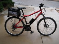
The bike is now completed enough to be my main commuter. I have ridden it to work three days in a row with no problems. The round-trip distance is 15.5 miles.

GiantEbikeRightViewV2.jpg

-- Joey
 
I forgot to mention that I tried mounting the controller in one of the side pockets of the trunk bag. The side pocket was well insulated and the outside only felt warm to the touch after a ride of a few miles. However, when I opened up the pocket and touched the controller box, I discovered that it was so hot I couldn't keep my finger on it for more than a second. Although the controller didn't fail, I thought it prudent to relocate the controller to a place where it could get direct air flow. In its new location in the frame triangle, it hardly even gets warm to the touch after a hard ride.

-- Joey
 
Good narrative. :D

You might add a waterbottle cage to the controller to distract the casual passerby... "for warming cocoa" or some other BS. :twisted:

Where did you source the fuseblock? That's nicely adapted. :mrgreen:
 
Hi guys, thanks for the feedback.

DJ & TD: I found the fuse block at Autozone in the electrical parts isle where you find switches, fuses, and connectors. I had an unusual assortment of parts in hand when I got to the checkout counter. The gentleman behind the counter took it upon himself to guess what I was up to. Electric bicycle wiring was not on his short list.

vanilla ice: The eight battery packs weigh a total of 18 lbs according to my digital bathroom scale. I haven't weighed the fully loaded trunk bag, but I don't think the fuse block, connectors, cutoff switch, wires, and bag add more than 1/2 lb. The bike's weight balance is rather poor. I have 8.5 lbs of motor and 18 lbs of batteries over the rear wheel so the weight is biased rearward considerably. The controller is in the frame triangle but it doesn't help much. I would have preferred to put the batteries within the frame triangle but the Milwaukee packs are a bit bulky and it looked easier to try a rear rack mount first. I'd like to keep the batteries in their original packaging to maintain the warranty. I use the bike for commuting to work and I'm able to stay on paved bikepaths and roads. The bike handles well enough for that environment. I do try to avoid fast turns. One time I accidently drove through a dip in the road at too high a speed and got airborne coming out of the dip. The front end stayed up longer than the back end and the landing was a bit exciting. I now take dips slower too.

-- Joey
 
I found a very good source for fuse blocks on the web -- wiringproducts.com. Navigate to their home page, click on "Fuses and Accessories" then select "Fuse Blocks". I use their ATO/ATC Ganged Fuse Blocks With Ground Bus. I purchased a small assortment of fuse blocks on their site and received prompt delivery to my home address (US). I selected "lowest-cost shipping option" which turned out to be USPS priority mail.

I have since updated my fuse block on ebike #2 to one with more inputs and a ground bus.

FuseBlockWithGroundOnEbike.jpg

This fuse block supports 8-to-1 connections which allowed me to try an experiment. I temporarily wired eight 28V Milwaukee battery packs in parallel to see how my e-bike would perform. The top speed was only about 16 mph and it was very slow going up hills. I had intended to use a 3pdt toggle switch to allow me to select between 1s8p and 2s4p configurations on the fly but the 1s8p 28V configuration was just too slow so I didn't bother to install the switch. I might try this approach again with 36 volt packs sometime to get 36V/72V but for now I'm limited to 28 volt packs and it is just better to keep them in a 2s configuration at 56V.

-- Joey
 
That's a sweet build Joey! Thanks for sharing. That bag of yours and the saw job look like they work great! I'm going to be upping from 6 to 9 Milwaukee packs/3s3p soon and am brainstorming on ways to get all those packs to fit somewhere on my old Jamis. :mrgreen:
 
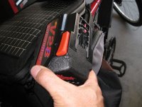
The batteries are tightly packed in my trunk bag and it is difficult to slip the connector blocks onto or off of the battery packs while they are seated. I need to reach the red-colored latches on the sides of the Milwaukee V28 battery packs to ensure that they have "clicked" when the connector blocks are attached. Otherwise, the connectors may not seat properly and result in an open circuit. Furthermore, the latches must be pressed inward in order to release the connector blocks from the battery packs. They are nearly impossible to reach while the batteries are seated in the trunk bag. This forces me to attach and remove the connector blocks to the battery packs without them being fully seated in the trunk bag. Unfortunately, the wires that come with the connector blocks are not very flexible and the insulation has low resistance to abrasion. They were beginning to look tattered after awhile and I was afraid that something could short eventually. I have been looking for a better solution for removing and installing the battery packs and connector blocks and have up with two alternatives.


Appoach #1:
--------------

Unfortunately the connector blocks that I was able to purchase only have two leads. However, the Milwaukee V28 battery packs have flat metal prongs that are compatible with standard automotive quick-connects. I made adapters for all eight battery packs using automotive quick-connects and Anderson powerpoles. The wires and connectors were secured in place using RTV. The adapters are shown in the following figure before RTV was applied.

ThreeWireBatteryConnection.jpg

I also modified my four Milwaukee chargers to include Anderson powerpole connectors. I used trailer-style wiring splitters to connect the three external wires to the internal circuitry. The external wires exited the charger through a subset of the ventilation holes on the bottom side.

ChargerInternalAdditions.jpg

ChargerWithThreeWireConnector.jpg


Approach #2:
----------------

For this alternative, I shortened the leads on the connector blocks, bent the leads 90 degrees, attached them to Anderson powerpoles, and add some RTV to protect the leads from wear and tear. I then built a pair of wiring harnesses, one for each of the two 4p groups of packs, and routed them from the trunk bag main compartment to the fuse block in the side pocket.

NewBatteryConnector.jpg

I should mention again that these connector blocks have been thinned so they fit within the dimensions of the battery packs when installed, except that the leads extend beyond the end of the battery pack. Here is what one of the connector blocks looks like when attached to a battery pack.

View attachment 1

Finally, here is what the batteries now look like with the adapters and wiring harnesses attached.

BatteriesInBikeWithNewConnectors.jpg

Although the second approach would seem to be more complicated due to extra adapter pieces, I actually prefer this to the first approach. The harnesses disconnect quickly and the batteries can simply be pulled out without worrying about side latches. When it is time to charge the battery packs, I simply pop off the connector blocks, set them aside, and slip the battery packs onto their chargers.

-- Joey
 
This begins the final chapter of my ebike #2 saga. After commuting to work on the bike for about 6 months with no technical problems, I finally fried the 400W BMC hub motor. I was running it at 56V with 35A controller which was about 5x its rated power. I wish I had taken a photo of the charred internals for posterity. :D

I purchased a 600W BMC-V2T rear hub motor in 26" wheel from cycle9. Kudos to Morgan and Elise at cycle9 for answering my questions about phase wire gauge, insulation, and sprocket teeth, and the timely delivery of a gang-buster motor. I wanted 11 teeth on the smallest sprocket of a 7-speed set. Morgan couldn't find one so I got it from Justin and friends at ebikes.ca. Here is a photo of the 600W BMC with the 7-speed sprocket attached.

SprocketOnMotor.jpg

After testing the motor with an old 20A BMC controller and throttle, I changed the motor wire connectors to Anderson powerpoles on the phase wires and a so-called "mini-XLR" connector for the hall wires for compatibility with my Crystalyte 24-72V 35A controller.

View attachment 2

Connectors2.jpg

I had a brake disk and torque arm left over from the 400W BMC hub motor which fit the 600W BMC motor nicely. Replacing the motor wire connectors gave me an opportunity to slip the torque arm over the bare wires. Although I'm using v-brakes on the rear, I wanted the brake disk screws in place to keep out moisture. The screws were too long without the disk so I included the disk.

BMC600andTorqueArm.jpg

Joey
 
Here are the final touches on ebike #2, starting with a double kickstand.

DualKickStand.jpg

I also added LED lights with integrated DC-DC converters from ebikes.ca; and a classic warning bell.

Headlight_CA_Bell.jpg
View attachment 2

Next, I added a pull switch for the lights and mounted it beside the existing 50A toggle kill switch. I decided
to use some spare "mini-XLR" 5-pin connectors for the front and tail light so I can easily disconnect them
from the rear trunk when I want to remove it.

LightSwitch.jpg

Here is the "final" version of ebike #2. The tires are Schwalbe Big Apples

UpdatedBike2.jpg

Joey
 
I can only give you some casual observations in comparing the first BMC rear hub motor I purchased (apparently these are now called BMC-V1 motors by some) to my new BMC V2-T rear hub motor from cycle9.com.

(1) I haven't fried the new BMC V2-T motor using my 56V Li-Mn pack and Crystalyte 35A analog controller which is something I can't say about my BMC-V1. The BMC V2-T motor comes with teflon-insulated 14 gauge phase wires whereas my BMC-V1 did not. I think the motor windings have a slightly thicker gauge on the V2. The folks at cycle9.com told me it could handle more power than the V1 and I believe it. I burned out the internal wiring on the V1 a few months after upgrading the phase wires to teflon insulated 14 gauge. I remember reading somewhere on this forum that the V1 should not be operated at more than 48V and 20A. I was operating it way over that limit. The BMC V2-T is still going strong at ~56V with 35A controller limit. I only draw full power (1900W+) when accelerating from a stop. I do spend some time at continuous 1200W draw when I'm in a hurry to get home (a long steady climb), but when I'm cruising, I draw less than 900W.

(2) For both the BMC V1 and BMC V2-T, I had to replace the phase wire and hall wire connectors to Anderson powerpole and so-called "mini-XLR" connectors for compatibility with my controller. This was expected and gave me the opportunity to slip on a torque arm on the wire-exit side of the axle before attaching the new connectors. I typically put the torque arm on the wire-exit side of the axle since the derailleur mechanism usually gets in the way of the torque arm if I try to mount it to the other side of the axle.

(3) Acceleration with the V1 at 35A/56V was moderate and steady all the way from a dead stop. Acceleration with the V2 at 35A/56V starts out moderate but at somewhere around 10mph, it starts to pull noticeably harder than the V1. The V2 makes a louder groan when it starts from a dead stop. I tried an experiment some time ago where I rewired my Milwaukee V28 battery pack to 1s8p (28V) and went for a spin. I tried the 28V configuration with the V1 motor and was very disappointed. The motor really bogged down when climbing modest hills and would slow to a crawl under load. I tried the 28V configuration again recently with the V2-T motor and was pleasantly surprised. The average speed at 28V was 15.9 mph on the flats and it chugs uphill quite well, typically slowing to 12 mph. I have since added a 3PDT switch to toggle between 28V and 56V. When I e-bike with my wife, who doesn't like to go over 15 mph, I switch my ride to 28V configuration and find it easier to keep at a modest pace that she appreciates.

Joey
 
Good info Joey. I am pushing my V1 motor ever since using it to haul windsurfing gear up rather steep hills. Steady state 900-1000 watts with bursts up to 1200. The evidence is scorching of the cloth insulators at the windings. Still working fine but am considering a spare. Do you now if the motor core of the V2 can fit in the V1 housing? I am already using a V2 planetary gear cluster in my V1. This would avoid relacing or buying a whole new wheel.
 
They said it would fit. The only difference in housing are the spoke holes larger on the new version. So, there may be the possibility of just buying the 600 watt core and swapping it in or just buying a 600 watt hub and using the core inside. What are you doing with the fried motor?
 
Back
Top