Sorry for bad english.
I have on hand
PMSM motor
New Controller Kelly KLS-8080IPS
Magnetic encoder RLS RM58
Before buying the controller, I asked Fany about the compatibility of the controller and the encoder, received a positive answer
I've been fighting with the controller for a week now. "Hall Err" error pops up all the time
1) I didn’t fully understand how the formula for calculating hall zero point and Line hall amplitude works
Twice asked Fany for a step-by-step guide, but she only gives ready-made numbers. I tried to check the calculations by reverse calculation, but I get slightly different numbers.
2) At the moment, she began to assert that it is not possible to replace the hall sensor with sin / cos and vice versa. If the motor is made by the factory for the hall sensor, then it will not work with sin / cos.
Using Sin/Cosin monitor software from Kelly
i got this data
Min
HB_AD 101
HA_AD 103
max
HB_AD 209
HA_AD 202
According to the formula from Kelly
Please rotate the motor shaft by manual for a fewcycles.Then please record the min and max value of either of Ha or Hb.Here is the formula to calculate the line hall zero point and amplitude.
Zero point=1023*((Min+Max)/2)/255
Amplitude=1023*(Max-(Min+Max)/2)/255
I got
Zero point=632.8
Amplitude=198
As I understand it, these are the minimum and maximum values sine/cosine signals in the number form , the controller recalculates them into voltage in accordance with internal logic.
and here are the numbers I got from Fany. They very close to mine
"According to the values you provided,here is the correct value for zero point and amplitude in user program.
Zero point:622 and Amplitude:217"
Also, in the controller i can set the "error" points for Zero point and Amplitude, they are called "Line Hall high" err and "Line Hall Low Err" I set them to +50 digits from the values I received from the formula. 632+50=682 and 198-50=148.
after that I have to pass identification angle operation
it always ends well
but i always get the error "Hall Err" and the controller won't start
I suspect that most likely all components are no have trouble. The problem is in numbers
The manual have another formula for setting the values of the Zero point and Amplitude sensors by Voltage
here she is
"Usually we just need to configure two parameters in user program according to the specification
of Sin/Cosin speed sensor.Please click Motor button in the user program.
Line hall zero:The line hall zero point is at 3Vdd/5=3*5V/5=3.0V.So we need to fill
3*1023/5=613.8=614 for Line hall zero parameter instead of 508 in the user program.
Line hall amplitude:The document showed the Amplitude is 1.1V±0.2V.We think the amplitude
is 1.1V for now.So we need to fill 1.1*1023/5=225 for line hall amplitude instead of 410 in the
user program. So output range of Sin/Cosin speed sensor is 3-1.1V=1.9V to 3+1.1V=4.1V.(1.9V-4.1V)"
But I don't understand how it works.
Those support, as I said above, is silent. And he claims that I have the wrong motor and sensor, and in general I'm like a stupid
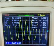
the last time I measured one of the sin/cos signals of the sensor with the oscilloscope in the photo.

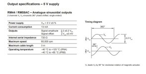
Data sheet my Magnetic encoder RLS RM58

and one more thing. Is there a difference between sine and cosine signal. If I mix up the wires in the connector. But in my opinion there should be no difference, they are sinusoids in the end, just shifted by 90 degrees ?!
I have on hand
PMSM motor
New Controller Kelly KLS-8080IPS
Magnetic encoder RLS RM58
Before buying the controller, I asked Fany about the compatibility of the controller and the encoder, received a positive answer
I've been fighting with the controller for a week now. "Hall Err" error pops up all the time
1) I didn’t fully understand how the formula for calculating hall zero point and Line hall amplitude works
Twice asked Fany for a step-by-step guide, but she only gives ready-made numbers. I tried to check the calculations by reverse calculation, but I get slightly different numbers.
2) At the moment, she began to assert that it is not possible to replace the hall sensor with sin / cos and vice versa. If the motor is made by the factory for the hall sensor, then it will not work with sin / cos.
Using Sin/Cosin monitor software from Kelly
i got this data
Min
HB_AD 101
HA_AD 103
max
HB_AD 209
HA_AD 202
According to the formula from Kelly
Please rotate the motor shaft by manual for a fewcycles.Then please record the min and max value of either of Ha or Hb.Here is the formula to calculate the line hall zero point and amplitude.
Zero point=1023*((Min+Max)/2)/255
Amplitude=1023*(Max-(Min+Max)/2)/255
I got
Zero point=632.8
Amplitude=198
As I understand it, these are the minimum and maximum values sine/cosine signals in the number form , the controller recalculates them into voltage in accordance with internal logic.
and here are the numbers I got from Fany. They very close to mine
"According to the values you provided,here is the correct value for zero point and amplitude in user program.
Zero point:622 and Amplitude:217"
Also, in the controller i can set the "error" points for Zero point and Amplitude, they are called "Line Hall high" err and "Line Hall Low Err" I set them to +50 digits from the values I received from the formula. 632+50=682 and 198-50=148.
after that I have to pass identification angle operation
it always ends well
but i always get the error "Hall Err" and the controller won't start
I suspect that most likely all components are no have trouble. The problem is in numbers
The manual have another formula for setting the values of the Zero point and Amplitude sensors by Voltage
here she is
"Usually we just need to configure two parameters in user program according to the specification
of Sin/Cosin speed sensor.Please click Motor button in the user program.
Line hall zero:The line hall zero point is at 3Vdd/5=3*5V/5=3.0V.So we need to fill
3*1023/5=613.8=614 for Line hall zero parameter instead of 508 in the user program.
Line hall amplitude:The document showed the Amplitude is 1.1V±0.2V.We think the amplitude
is 1.1V for now.So we need to fill 1.1*1023/5=225 for line hall amplitude instead of 410 in the
user program. So output range of Sin/Cosin speed sensor is 3-1.1V=1.9V to 3+1.1V=4.1V.(1.9V-4.1V)"
But I don't understand how it works.
Those support, as I said above, is silent. And he claims that I have the wrong motor and sensor, and in general I'm like a stupid
the last time I measured one of the sin/cos signals of the sensor with the oscilloscope in the photo.

Data sheet my Magnetic encoder RLS RM58

and one more thing. Is there a difference between sine and cosine signal. If I mix up the wires in the connector. But in my opinion there should be no difference, they are sinusoids in the end, just shifted by 90 degrees ?!

