Lipo to Bestek D167 wiring

standfast

100 W
Joined
Apr 25, 2014
Messages
124
Location
Los Lunas, New Mexico
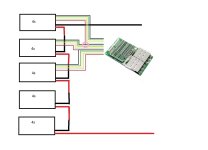
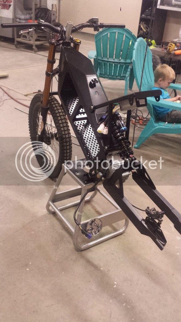
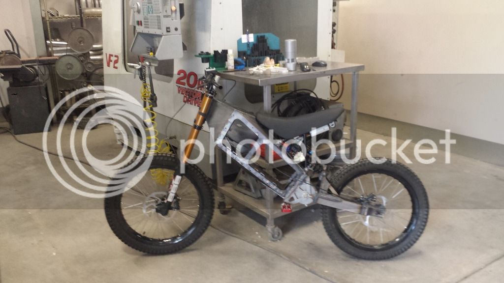
I am lacking confidence with wiring this. When I have the 4s packs connected in series to charge through the BMS using a 20s (84v) power supply, how do I wire the balance leads that overlap? Ie. should the positive leads from the first pack tie into the negative lead from the second (as seen in my attached drawing in the pink circle) and so on or do they not need to be tied together because the main lead already does that? Also I am unsure of where I should pull my negative leads from to tie into the BMS and where to tie them in. Sorry for the newb question. I have the bike done and this is my last hurdle to get on to riding this thing!
 

Attachments

  • serieswiring.jpg
    serieswiring.jpg
    49.1 KB · Views: 682
It is correct way. Depending how old your bms is, it has different wiring. I have bought couple new ones and instead usual 17 balancing wires it has 16 for 16S bms. It gets B- balance wire from main B- connection.
 
you have 5 sense wire to the JST plug. the first wire is B0 for that pack and the top wire is B4 for the pack. you should take all the packs apart and cut off the shrink wrap and put all 20S into compression using hardboard end. plates and then wrap with duck tape and wrap with zip ties or inside a box with ends that keep all the pouches in compression. as much compression as you can create.

i recommend cutting off the large cables that terminate the packs and connect the pack end to end by soldering the end tabs to each other. leave the two terminal wires intact so you have a B+ and B- for the pack and then you would connect the B- to the BMS.

remove all of the sense wires by clipping them where they are soldered to the tabs and then solder each of the sense wires for the D167 to each of the solder spots left behind where the sense wires were soldered to the tab. by soldering to that residual solder from the old sense wires then you can create a good solder joint. cover each by folding that piece of plastic shielding back down over the new sense wire solder spot and then you will have a real battery that will last longer than the regular pouch packs sinc ethe compression will extend the cycle life of the pouches.
 

Attachments

  • DSC01800.JPG
    DSC01800.JPG
    101.6 KB · Views: 2,279
  • DSC01804.JPG
    DSC01804.JPG
    54.1 KB · Views: 2,279
  • DSC01849.JPG
    DSC01849.JPG
    63.4 KB · Views: 2,279
Yes, you should tie the positive red sense wire of pack 1 to the negative sense wire of pack 2, etc. Relying on just the main series connection will result in minor voltage differences. if you're not worried about that small difference, then don't worry about connecting the sense wires together. I'd wire the sense wires and main leads where all I had to do was plug in the sub packs to plugs on the bms. That way you could replace on are all of them in a matter of minutes if there was a problem or when you wanted fresh batteries. It's also how I set up my 24s2p pack using 4s hardcase packs and I haven't had a problem with it in 3 years of use.
 
dnmun, I like what you did there! That makes it very clean. Couple of issues though is I have 4s Hardcase and I kind of like the protection that provides for the rough ride. Second being I only want to use the BMS for just charging so it is not going to be permanently mounted on the bike. I am using this http://www.digikey.com/product-detail/en/PT06A-16-26P/PT06A-16-26P-ND/2510867 26-pin MIL connector to connect all the sense leads and the main leads using 2 pins each for the + and - main leads. On the charger side of that connector I was going to "T" off the sense leads to also run to 3 8s Cellogs to check the balance of each cell before ever charge. The charger I will be using is this one http://em3ev.com/store/index.php?route=product/product&path=37&product_id=153 that I opened up and adjusted the voltage down for 20s. The charger has 3 position switch that sets output voltage at 84v, 82v, or 76v. 84v setting to get the cell voltage up to 4.2 to kick in the BMS, 82v to bulk charge, or 76v for storage. I assume all of this will work correctly. The idea of this setup came from Tench but he hasn't been around lately to ask questions. Does the BMS only kick in once a cell reaches 4.2?
 
dnmun said:
that charger will not balance your battery because it has a latching output so it turns off when it reaches final voltage.

I can adjust the output voltage on the charger. What if I bump it up a little bit to 4.28v per cell (85.6) or something like that? That way it can hang in the balance mode up to that point. I assume the balance function of the BMS doesn't start until the cell hits 4.2v per cell? Not sure. If that is not feasible then what charger do you recommend?
 
no, it will not be in balance mode if you raise the voltage. you will not be able to change the final voltage for that charger.

if your only interest in the BMS is for charging then you could just use that charger without the BMS anyway. the BMS is there to protect the battery from over discharge and shorted output so in refusing to use it you lose the most useful functions it provides.
 
What do you mean? I already changed the final voltage of the charger. I adjusted it from 21s that it came with to 20s voltage. EM3EV provided instructions on how to do it. It was pretty simple. There are trim pots that allow you to adjust it.

I wanted to use the BMS to balance the packs when necessary so I don't have to remove all the packs from the bike. It will be much easier if I don't have to remove the packs from the bike. It does not allow enough amp draw for me to use it on discharge so I wanted to just use it to assist in balancing when it looks like it needs it based on the celllog readings each time I plug it in. So when does the BMS go into balance mode? How is it triggered?

Also, doesn't the BMS provide added protection when bulk charging though it?
 
The bms doesn't have a balance mode per se. It just Starts bleeding cell voltage at the top when the set voltage is hit. Any charger that will provide enough voltage to do that will work as long as it provides a constant voltage and doesn't shut off at that voltage. The bms doesn't care one bit what type charger it is as long as it provides the amount of voltage needed. Anyone that tells you different is just full of crap. RC chargers that do have balance modes can balance the cells at any voltage. You might want to consider using 5 battery medics for charging. One for each 4s parallel group. they provide a real balance mode also, and/or can have the bleed voltage set at whatever you want.
 
This is how I planned on wiring it for charging. Does this look correct other than the charger potentially not working for this that is? I assumed the BMS would provide additional safety through individual cell monitoring while bulk charging by shutting off if a cell's voltage got too high. Isn't this better than just bulk charging without monitoring it? I just took a look at the battery medics. Should I just put battery medics in place of the cell logs for balancing?

serieswiring_zpsg9cfetlx.jpg
 
you should ask your expert about how much imbalance the battery medics will cause. he knows more than anyone about them i expect.

i never monitor the cell voltages and just plug in and charge and let the BMS do the work. never did understand why people become slaves to charging.
 
dnmun said:
you should ask your expert about how much imbalance the battery medics will cause. he knows more than anyone about them i expect.

i never monitor the cell voltages and just plug in and charge and let the BMS do the work. never did understand why people become slaves to charging.

I am new here and trying to learn. I don't know who the expert is. I am just trying to figure out how to charge using the BMS because I assume it offers more protection than just bulk charging which your last statement makes me assume that it does. Does it? Your earlier statements make me assume that it is pointless to use the BMS for charging only. Apparently I have the wrong charger for the BMS but I don't know what the right one is? I know someone has to know these answers here yet there seems to be something personal going on here? I dunno. I just wanna figure this out, get the parts I need, and confirm that my wiring diagram is correct so I can ride the damn bike! :mrgreen: I have been reading myself in circles (endless-sphere) on this forum about lipo charging, components and opinions.
 
What's the max draw from the controller going to be? The D167 is rated for 35A. If that's not enough, just get another bms rated for the amperage you need. They make them for up to 250A. Then just use the bms normally and forget the cell logs. Get a cheap voltmeter to monitor pack voltage. That's what I'd do today if I didn't already have an rc charger setup. Or just hook up what you have normally and then parallel discharge wires from the battery pack if you want to bypass it for discharge and hook a voltmeter to the bms discharge. It a cell goes low, the voltmeter voltage should drop.
 
Your diagrams appear to be functional but there's really no need to connect the redundant wires in the pink circle. I use JST extension harnesses, move contacts into other housings and usually shrink wrap and tuck the redundant balance wires/contacts safely away.

It's mind boggling at first because when creating a series string from several bricks there's many more balance wires than you'll need for the BMS channels. Go slow, go careful. Check and double check with a DVM but it will eventually make sense.

Tapping or parallel connections for celllog is nice but adds more rework. I made a couple adapter "dongles" that allow me to tap a CellLog or BM6 on balance leads but only use it once in a while.

My thing is to leave the 4S hardcase unmolested so I can preserve any warranty and merely replace using stock bricks. JST extension harnesses are my friend. Silicone wire versions, btw. I don't like the cheaper stiff plastic insulation. Buy several and hack to fit your situation.

Not sure about your charger issues? I use anything that gets close to top charge voltage. Balancing with my D167 BMS @ 84mA is too slow for 5-10-15Ah cell groups IMO. If something needs balance I find out why...
 
I am using a Kelly KBS7221X and it has 55A continuous with 130A 10sec boost. I thought I could get away with no LVC by monitoring voltage on the CA while riding and paying attention to the cells before and after charging to spot trends. That's why I got the smaller 35A BMS for charging only. I just wanted something to monitor the cell voltage while charging to make sure none exceeded 4.2 when charging. I guess it doesn't work that way? Seems like it should.

What charger is available to use with a 20s Bestek BMS that doesn't shut down so the BMS can do it's thing?
 
Ykick said:
Not sure about your charger issues? I use anything that gets close to top charge voltage. Balancing with my D167 BMS @ 84mA is too slow for 5-10-15Ah cell groups IMO. If something needs balance I find out why...

Thanks ykick, I kind of figured that it would not be able to bleed off voltage enough to handle significant imbalance based on the 84mA. What is your strategy for getting a low cell back up to test it?
 
Ykick said:
Your diagrams appear to be functional but there's really no need to connect the redundant wires in the pink circle. I use JST extension harnesses, move contacts into other housings and usually shrink wrap and tuck the redundant balance wires/contacts safely away. [/quote

Ykick are you saying you dont need to connect those wires? Which become redundant?

Thanks
 
littleskull99 said:
Ykick are you saying you dont need to connect those wires? Which become redundant?

Thanks

It's because the main leads are already series connected so it becomes redundant because those wires come from the same point inside the pack as the main leads. I wasn't sure if it mattered or not.
 
standfast said:
Ykick said:
Not sure about your charger issues? I use anything that gets close to top charge voltage. Balancing with my D167 BMS @ 84mA is too slow for 5-10-15Ah cell groups IMO. If something needs balance I find out why...

Thanks ykick, I kind of figured that it would not be able to bleed off voltage enough to handle significant imbalance based on the 84mA. What is your strategy for getting a low cell back up to test it?

Once I'm satisfied a lower voltage cell isn't dangerous (leaking, puffy, extremely high IR, etc.) I charge low single cells through the appropriate balance channel wiring. Often using my iCharger but I've also re-purposed cell phone 3.7V battery BMS circuits with pigtails to charge single Lipoly cells using any USB port or 5V wall charger.

Those single cell BMS are pretty handy and plentiful. Just rip out of an old Cellphone battery pack and wire it to your connector ecosystem. Simple pins to insert into the battery pack JST plugs. Or, just use an RC charger on 1S setting and keep the current under 2-3A for those small wires.

EDIT - Sorry, I didn’t comment on your output setup. Yeah, D167 isn’t gonna handle that controller output. Kind of a waste but you could use the D167 for charging only - you’ll merely need separate charge/discharge connectors. Bypass the BMS for discharge, connected in-line to charge.

Here's a small 16S pack assembled with hardcase bricks and JST extension harnesses:16Sbattery.JPG
Nothing was cut, soldered, or molested to achieve the connections. All I did was move contacts from the 4S (5 pin) JST’s over to 8S (9 pin) JST housing.
 
Ykick said:
EDIT - Sorry, I didn’t comment on your output setup. Yeah, D167 isn’t gonna handle that controller output. Kind of a waste but you could use the D167 for charging only - you’ll merely need separate charge/discharge connectors. Bypass the BMS for discharge, connected in-line to charge.

The way I was planning on wiring it, the BMS is not going to be on the bike. A 26 pin MIL connector would be somewhere on the bike to hook up all balance leads and the charging leads (using 2 each of the 7.5A rated pins for charging). Then on the bike I would just monitor total pack voltage on the CA while riding and check celllogs at the charging station before and after each charge to see if any are going out of balance. Maybe put a single celllog on the bike focused on a pack with a cell that trend lowest and use that as a fuel gauge?

I suppose I can order the 250A BMS from them at some point and leave it on the bike. I suspect it won't be cheap like the smaller units though. I am gonna get a quote for one now to see.

I know it's somewhat wasteful to use the D167 in this way but it still seemed like the cheapest way to get individual cell monitoring to prevent overcharging a single cell while bulk charging a pack that you don't want to remove from the bike every time. As you can see, the battery will be captive in the frame.

20150513_204133_zpsxpcqgxt1.jpg

20150512_181622_zpslbxzrxvr.jpg
 
Serious machine. It’s not much of waste but you could’ve used a smaller, cheaper BMS for charging only. At least you're good up to 35A charge current, LOL...

I’ve considered doing similar from time to time - charge only protection. There might be a hack to utilize the BMS as an “alarm” controller for discharge? But I dunno the output design enough to figure that one out…

Good luck my friend…
 
to use the BMS as an alarm you would use an led that was grounded through the output mosfets so that the led would turn off when the battery was over discharged. you could continue using the battery then without interruption. put a resistor in the led lead so you can at least save the led from burning up.
 
Back
Top