
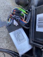
Anyone familiar with this controller from my Arrow 9 with a 500 watt motor 48V 29 AH battery? There's a floating white wire with a pin not connected to anything. Also a black 2 pin connector and 3 pin white connector harness that is not connected. I will check the unused wiires with a volt meter later and see what I find.
You are using an out of date browser. It may not display this or other websites correctly.
You should upgrade or use an alternative browser.
You should upgrade or use an alternative browser.
Looking for info on controller for my Arrow 9 ebike
- Thread starter Zambam
- Start date
The unused 2 pin black connector's blk/wh and pur wires gets 48 v across it when I turn on the headlight. My bike does not have a taillight. Would it be safe to use that 48V for my aftermarket taillight (it is rated for 48V)?
The unused white connector is a 5 pin connector with 2 empty pins, so only 3 pins are used. With DVM negative terminal connected to the blk/wh wire, the gn wire gets 5V and the wh/yel wire gets 3.2V with key on. Any idea what these voltages are for?
The unused white connector is a 5 pin connector with 2 empty pins, so only 3 pins are used. With DVM negative terminal connected to the blk/wh wire, the gn wire gets 5V and the wh/yel wire gets 3.2V with key on. Any idea what these voltages are for?
Adrian_
10 W
- Joined
- Apr 12, 2022
- Messages
- 84
Theoretically you could but it's possible that the 48v output is a signal output and it wasn't designed to output current or atleast high enough current to power a light. If it was me, I would play it safe and use those wires to turn on and off a high trigger signal relay that would power a light unless someone can confirm that those aren't singal wires and it's safe to draw some current from them.The unused 2 pin black connector's blk/wh and pur wires gets 48 v across it when I turn on the headlight. My bike does not have a taillight. Would it be safe to use that 48V for my aftermarket taillight (it is rated for 48V)?
Good point, thanks! I buzzed out the wires betweenn the unused 2 pin connector to the headlight/ horn connector of the controller and confirmed the 2 blk/wh & pur wires are internally connected within the controller (wires same color). I should be ok wiring up the night tail light to it.Theoretically you could but it's possible that the 48v output is a signal output and it wasn't designed to output current or atleast high enough current to power a light. If it was me, I would play it safe and use those wires to turn on and off a high trigger signal relay that would power a light unless someone can confirm that those aren't singal wires and it's safe to draw some current from them.
There are also turn signals and brake light that's available that I'd like to add which will require more buzzing.
What kind of switches are typically in the brake levers? (both levers cut power). I don't really want to take one apart to find out. Can the brake lever signal be used to activate the brake light?
Attachments
Adrian_
10 W
- Joined
- Apr 12, 2022
- Messages
- 84
It's typically two wires going into each level with the switch inside completing the circuit and connecting both wires together. They are either a 'low level' system which means one wire is ground other one is signal, when ground is connected to signal by the switch inside the lever then the controller sees that as brakes enabled. There's also a 'high level' system which is the same as low level but instead of using ground, it's 12v.What kind of switches are typically in the brake levers? (both levers cut power). I don't really want to take one apart to find out. Can the brake lever signal be used to activate the brake light?
On some controllers it says which system it is on the controller label like here:

But if your doesn't then you can just use a multimeter to check, it's not end of the world. If your system is high level then you could just splice into the returning brake wire with no voltage when the brake lever is not pressed and power the brake light that way, if it's low level system then you could do the same or use a solid state relay.
Last edited:
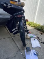
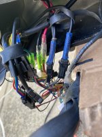
I propped the bike's rear wheel off the ground, unplugged connectors one by one, ran the throttle till I found the two connectors that did not cut power. It's the 2 connectors with gry and blk wires with blue masking tape marked "R lever & F lever". 2.8 volts sits across the gry & blk wires normally. When the lever is pulled, the 2.8V goes to zero volts.
Is 2.8 v non standard for ebike brake signal?
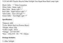
I don't think it has sufficient current to drive any kind of coiled relays. Take a look at the pin out of the brake light in the attachment above, it has its own 2 wires (white + & blue -) and does not share a common with the black wire "-" main connection. Any explanation for that? Any ideas on an interface to drive the brake light?
Is 2.8 v non standard for ebike brake signal?
I don't think it has sufficient current to drive any kind of coiled relays. Take a look at the pin out of the brake light in the attachment above, it has its own 2 wires (white + & blue -) and does not share a common with the black wire "-" main connection. Any explanation for that? Any ideas on an interface to drive the brake light?
Attachments
Adrian_
10 W
- Joined
- Apr 12, 2022
- Messages
- 84
I have seen controllers that use low voltage for brake sensors, typically ≤1 volt but from my experience they are not common, it's typically either ground or 12v. The easiest solution that I can think of is to use a low trigger relay to activate the brake lights, if you don't know what they are it's a relay with a signal input, when the signal input receives 0v or ground, the relay gets activated which in your case it would be perfect because when activating the lever, the 2.8v pulls to zero. However those relays commonly require 12v to work which would require you to get a dc-dc buck converter, you can get some that are really small like this one:I propped the bike's rear wheel off the ground, unplugged connectors one by one, ran the throttle till I found the two connectors that did not cut power. It's the 2 connectors with gry and blk wires with blue masking tape marked "R lever & F lever". 2.8 volts sits across the gry & blk wires normally. When the lever is pulled, the 2.8V goes to zero volts.
Is 2.8 v non standard for ebike brake signal?
I don't think it has sufficient current to drive any kind of coiled relays. Take a look at the pin out of the brake light in the attachment above, it has its own 2 wires (white + & blue -) and does not share a common with the black wire "-" main connection. Any explanation for that? Any ideas on an interface to drive the brake light?

I can think of other solutions to activating the brake light but they all require 12v and the low trigger relay is the simplest one. I don't think there's anything you can do with that 2.8v especially since it pulls to zero when activated.
Regarding the brake light wiring, I think it doesn't share a common ground probably to increase the compatibility, some systems use ground to activate brake lights, some positive input so no matter what system the consumer is using, they will be able to use the brake light. If the brake light had a common ground and a bike used ground to activate the brake light then non of the lights (running light and indicators) would work unless the brake lights are activated which would be silly.
Can you provide a link to a low trigger relay? Thanks!I have seen controllers that use low voltage for brake sensors, typically ≤1 volt but from my experience they are not common, it's typically either ground or 12v. The easiest solution that I can think of is to use a low trigger relay to activate the brake lights, if you don't know what they are it's a relay with a signal input, when the signal input receives 0v or ground, the relay gets activated which in your case it would be perfect because when activating the lever, the 2.8v pulls to zero. However those relays commonly require 12v to work which would require you to get a dc-dc buck converter, you can get some that are really small like this one:
View attachment 332694
I can think of other solutions to activating the brake light but they all require 12v and the low trigger relay is the simplest one. I don't think there's anything you can do with that 2.8v especially since it pulls to zero when activated.
Regarding the brake light wiring, I think it doesn't share a common ground probably to increase the compatibility, some systems use ground to activate brake lights, some positive input so no matter what system the consumer is using, they will be able to use the brake light. If the brake light had a common ground and a bike used ground to activate the brake light then non of the lights (running light and indicators) would work unless the brake lights are activated which would be silly.
Similar threads
- Replies
- 13
- Views
- 681
- Replies
- 11
- Views
- 879
- Replies
- 2
- Views
- 530
- Replies
- 0
- Views
- 488
- Replies
- 11
- Views
- 1,199