MAC motor damaged windings - what to do?

izeman

1 GW
Joined
Jun 21, 2011
Messages
5,132
Location
Vienna, Austria
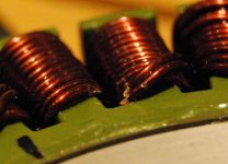
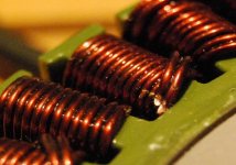
i was working at the motor today, and my colleague didn't take care and after the last hole drilled that drill hit the windings.
i can't say if there is a short (have to measure that), and can't really say if they are weakened a lot.
so if i sealed it with laquer/epoxy and reuse it (after checking for a short) what could i expect? will this winding burn through as it's too thin now for the current running through the motor? or will it run as normal?

the pictures are as good as my DSLR could make them:
DSC_9623.JPG

DSC_9624.JPG
 
i woulda filled the divot with solder before coating it with shellac. now it is not possible to fill the divot with solder since the shellac will prevent you from getting the solder to stick to the bare copper.
 
If the motor has been running fairly cool under your normal loads, it might be fine. I believe the two upper minor cuts only need epoxy to insulate them. If it has been running fairly hot, the two deeper cuts will run hotter at that cut spot than the rest of the windings, due to the lower copper mass. It is now as if there is a short section of thin wire connecting the ends of two fatter wires.

edit: I think it can be reliably repaired.
 
Here is a repair option that I think may be worth the effort. Bear in mind, if it proves to be too weak, you can always have the stator re-wound afterwards.

Buy a cordless Dremel, they are quite useful.

Grind away a portion of the sides of the wires that are damaged so as to expose the widest part of the wires diameter. prepare a section of wire to solder into the flat spot that you have made, and pre-tin the repair bit before setting it in place.

IsemanRepair2.png
 
Thanks for the tips guys. I wil try what Ron suggested. Are these two wires allowed to touch each other or do they belong to different phases (what I don't think). It will be easier to repair both of them with one bigger copper wire.
If it doesn't work I can try to do my first motor rewinding :)
 
Why on earth would someone drill holes with the side covers on, because the aluminum shavings need to be removed anyway and it's 10X better not to have them in the nooks and crannies of the stator and magnetic gap?
 
John in CR said:
Why on earth would someone drill holes with the side covers on, because the aluminum shavings need to be removed anyway and it's 10X better not to have them in the nooks and crannies of the stator and magnetic gap?
i don't know where you read something about mounted covers or something like that. we were drilling the m4 stator threads to make them m5. and there are no shavings left as everything was removed with an air compressor.
no everyone is drilling holes in their motors for air cooling ...
 
How a drill bit got close to the windings doesn't matter now. If you have space for the resulting connections, the poor copper fill on those stator teeth makes the repair fairly simple. Remove the copper from that tooth (note the direction and number of turns), overlap and join one end of a lower resistance bundle of magnet wire, wind the same number of turns in the same direction, make the other wire joint, tie the wires down tight and slather the area with high temp resin used for electric motors.

As long as you use an equal or greater amount of copper on each turn, get the turns right, and make good low resistance joints the motor can be as good or better than new. With most motors I've seen I wouldn't even consider trying, but there's so much excess space before getting to the copper of the adjacent teeth along with visible space between the strands on the factory winding, that getting the same or greater copper on each turn will be a simple matter. It really comes down to the splicing and clearance issues with the rotor.
 
Speaking of low copper fill wouldn't a rewind of the whole motor with more copper be the better solution? (Edit: I think this will not work as the windings as is are already really close to the side cover and the rotor)
If I understand you correctly you would suggest cutting the wire where the damage its, unwind the wire of the whole tooth and rewind it with new wire and then join the wire again. Correct? But I would need the same wire diameter and some resin to do the repair.
 
izeman said:
Speaking of low copper fill wouldn't a rewind of the whole motor with more copper be the better solution? (Edit: I think this will not work as the windings as is are already really close to the side cover and the rotor)
If I understand you correctly you would suggest cutting the wire where the damage its, unwind the wire of the whole tooth and rewind it with new wire and then join the wire again. Correct? But I would need the same wire diameter and some resin to do the repair.

I'd need the stator in hand to figure out the 2 places I would cut the wire wound on that tooth. I would want to leave enough length left to be able to make a overlapping joints. It's unclear to me what the 2 strands are. ie are the phases wound with 2 strands or just one? Are they the last turn or the first turn. If it's 2 strands in parallel and cut at the same point, then maybe you can repair it in place by scraping enough varnish off to solder a piece of copper to bridge the cut. If they are on the last turn, then maybe you can unwrap it just a half turn or a full turn to get some length to work with and splice in a repair without completely unwinding the tooth. The motor varnish may make that hard to do, because it's pretty tough stuff, so getting one turn off down at the root of the tooth may not work. Rewinding the tooth may prove easier.

The critical things are that you end up with the same number of turns wound in the same direction, and that you have no shorts. If you end up with more copper on each turn, then that tooth will run cooler than the others. As I understand larger gauge wire like the factory used is more difficult to wind tightly, so I would use thinner gauge wire and enough strands to have lower resistance than the original thick wire.

Sure a full stator rewind with better copper fill would make the motor better than new, but that may prove easier said than done. Getting more copper on one tooth is easy, because the adjacent teeth have a nice neat flat lay on them giving you extra space for the tooth needing the repair.

I misspoke before. It's not resin that you need. Motor varnish like the factory used is the thing to use to coat the repair and hold new wire firmly in place. The same place you source the magnet wire should have it.
 
Hmmm. I'd get some solid copper wire and use a hammer to pound it into a shape that will fit the divot. And some good wire cutters to cut & shave it down. Then I'd plate the divot and copper piece with solder and then join. Overlay with epoxy. What spinningmagnets said - since you have thinned the wire in that place, it'll have higher resistance and overtime weaken.
 
Sorry to see the damage.

It appears there are 14 strand-turns and two appear to be in parallel, so this appears to be a 7 turn motor. If that is the case those two strands can be shorted together and that might make your repair easier. I wonder if scraping away the varnish (not copper) and adding solder there would be enough. Perhaps a small piece of copper wire can be laid in there across both wires and that soldered in place. Solder is much higher resistance than copper so copper is preferable if possible.

Rewinding the tooth would be better as John indicated. The question then becomes placing the connections to avoid additional loss and possible shorts or scraping.
 
a lot of good advise here. the problem is, that i will never know if a repair did work. i can't measure the temp at the wire joint.
it's quite tempting to try to rewind the whole motor. something new to learn. i watched the video where chinese workers wind motors. they are incredibly fast. can't be that difficult ;)
but first of all i will have to study some background knowledge and theory. what copper to take, how to isolate the wires etc ...
 
you cannot rewind just one stator pole. unless you get identical wire it will not be possible to have the same impedance in that section of wire there anyway.

you should be able to examine the windings closely enuff to determine if the two wires are either in parallel on the same phase or if they are separate wires on the sme phase.

if the same phase then just solder the divot closed and it should do fine, just like i recommended initially. i thought you said you had put shellac on it so if not then the solder should stick and the biggest problem is to not overheat it so much that the shellac melts off on the underside when you solder into the divot.

so quick heat and faster with the sponge to cool it off afterwards.
 
As long as the wire has the same cross sectional area, or greater, it should work fine. If it is larger in cross-sectional area the resistance will be lower, but this is a small fraction of the total, and wire the proper size should not be hard to source.

Rewinding the whole motor is probably more work than you think, but is do-able.

Regarding knowing if the repair worked - if the motor opens a winding and fails, the repair didn't work. If it fails, you can then rewind it.
 
john was counting winding to determine the motor speed. i tried myself, but am not sure that i know what to count exactly. the windings are always in parallel. so what do i count? complete turns/winds? or the wires going to the next tooth as well?

here are pics of all three stators i have. i made pictures where counting could be most easily done.
anyone willing to count and tell me the results? ;)

IMG_0413.JPG

IMG_0412.JPG

IMG_0411.JPG
 
Back
Top