I did send this to my distributor to see if they can get Sevcon to help us out. If anybody already has answers to some questions dont be shy

Find attached my dcf, if this gets solved I will post the relevant information and updated dcf as well. (disclaimer: use dcf on your own risk blabla it can brick blabla can malfunction blabla can break something else blabla)
"
We would like support in solving our issues:
Setup information
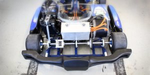
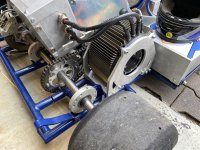
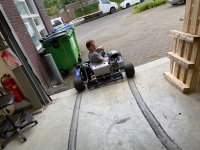
Application: Electric kart
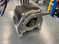
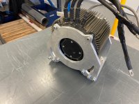
Motor: motenergy ME1616
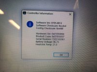
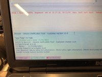
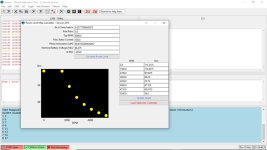
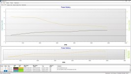
Controller: Sevcon gen4 size 6 80V with fluid coolplate, see pics for HW and SW versions
Battery: powerbattery 24S2P 60Ah fluid cooled continuous 480A - peak 720A nominal 86.5V (5,2kWh)
BMS: EMUS celmodules and canbus module
Contactors: 1x at BMS with economizer and 1x at controller without economizer
Cables / busbars: 50mm2
Fusing: 500A on controller and 500A in battery pack
Dcf: find attached
Issues we have:
• The UI software is, to say it politely, unstable and not very user friendly. The manual doesn’t help much in understanding it all: it focusses on setting up the basics to wire it up and get a motor to spin but the advanced settings are not covered. When we try google, we find that we are not alone in struggling with this.
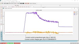
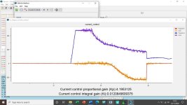
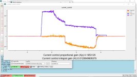
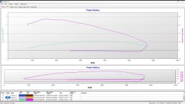
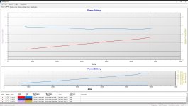
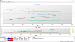
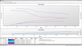
• Low power. After tweaking we get around 18 kW at DC bus amperage of 320A at 90V with field weakening. This means that 11kW disappears since we put 29kW into the controller. And even 29kW peak output would be fairly low. Without FW we have 11kW at 240A DC bus. Again we put in way more power then we get out: we put in 22kW which is double of what me measure at the dyno. See settings in the dcf and screenshot of the currents with and without FW. Driving it also confirms: not really fast. Geared for 130kmu as we expected double the power, not a strange assumption imo since a Zero motorcycle has 34kW, can reach that speed and has a similar setup with a sevcon, 100V and a motenergy alike motor. As what we have is a very common combination, we would expect a better baseline setup and a power output more in line with the specs.
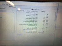
• Motor temperature not ok, the “overall DSP maximum motor T”. Goes up very quickly over 135’C, and goes back fairly quickly towards 100’C. 2 hours cooling down period after testing it still shows 80 ‘C while the outside of the motor is cold. A day later the motor is still 77’C which is of course not the case. We don’t even know if this represents the sensor value or is a calculation based on current, an excellent example of documentation being insufficient and software adding to the confusion. In any case we can’t figure out how to set this up but currently this is not ok, and we have no idea if we push the motor over the limit.
• We already had 3 times a failed inline fuse from contactor towards the controller. It is supposed to be 7A according to the manual, which we have. We measured current on that wire and see around 1A for 2sec during precharging, and after that 0.5A during operation. Seems normal to us, still it keeps failing during operation at times while nothing weird is going on. We are sure there are no shorts in the wire. We definitely did experiment with wrong settings and had cutouts and errors and spikey current graphs but that didn’t trip the fuse at least not at those moments. Any idea’s here? We can’t keep changing those and raising up the fuse value without knowing what is going on, is not the best practice.
• When we let go of the throttle, up to 250A was send back to the batteries while the limit was set at 90A. It seems that limit is not a control setting, just a warning level which gets ignored. When making current graphs we can see that the target Iq is indeed that level so the controller does so intentionally. It could even be higher since a dyno is not the same as driving. This is damaging for the batteries and a potential fire hazard. We reduced this regen current by setting lower rpm/s values for decelerating. Is this the intended way?!? This way setting up useful regeneration is virtually impossible. So we need to know the best way to limit battery currents and how to setup regen. Ideally both are just current settings but we don’t get that to work. Of course we guard current in the BMS, but that will open the contactor under high current every time we slow down so that is not an option.
What we tried to get the maximum power out of the controller:
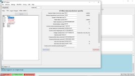
• Checking the sincos alignment. Seems to be spot on. In any case we tried a couple of degrees difference in either way, but have similar performance as before. When going 10 degrees of in either way we loose quite some power. So this seems to be ok. (what we don’t understand is why there are 2 values which can be changed…… We only changed the top one at 31 degrees and the bottom one of 2 degrees we didn’t. Could that be a sincos sensor calibration value to compensate for angle offset between sin and cos? And how is that determined?)
• We raised up the maximum current towards 650. That only helps with very low rpm torque and does nothing for max power. So we set that back.
• We raised up the nominal current from 300 to 400 and 500, doesn’t make a difference. Maybe this is a warning level but seems not a setting. (would be a good improvement in the software to make a distinction between “settings that influence actual control” and “safety limits which will stop the controller” and “warning limits which will only gives messages”)
• We checked if the throttle signal results in only half throttle or something. Seems ok as max throttle is set at 10V which we can reach, the high current at low rpm also indicates full throttle anyway.
• We tried current mode and speed mode. Apart from throttle behavior no real power changes.
• We took off all safety’s and limits we could find to be sure there is no hidden cutback active. No change in power output.
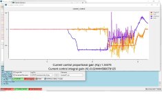
• When increasing Kp we see torque increase especially at lower rpm, however a strange shrieking noise comes out of the motor and we have large spikes in the current graph. That doesn’t look/sound right so we did set it back to 4 which is the highest setting without those issues.
• Played with field weakening, however from run to run the current graph is completely different: sometimes we have FW from almost zero rpm and sometimes from halfway the rpm, sometimes not at all. Most of the time the transition into FW is very obvious as suddenly torque and thus rpm increases faster when FW gets active. Using the macro “field weakening” it sets the Id to -229A which we guess it calculates based on existing motor parameters. We played with this value but higher gives no power increase nor any noticeable change, and lower gives a decrease. In any case not clear how this needs to be setup to work properly for max power, and for smoother operation.
• We used the macro “max power” which apparently sets only the rpm/torque table to max torque settings. No power increase, only current failures in combination with FW especially on low resistance runs where rpm goes up quickly. So how this is supposed to help get more power is unclear.
• Try other users to see if they can help us. Unfortunately sharing dcf files with others is tricky since many controller hardware and dld versions are available. We tried to learn from setups from others but to no avail. We didn’t dare to flash the dld as we fear to brick the controller doing so, especially since we are not always sure it the dld we get from others matches our hardware.
• Getting desperate, we tried varying settings which we don’t fully understand, like the motor specific setup and gains. No real changes when varying that, except less smooth operation and a bit less power. We did only 1 step up and 1 step down but since nothing made an increase in performance we didn’t try extremer settings.
"
