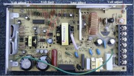
I have a meanwell s150 psu. In the originale thread is explained
*When run in "series" the DC "negative" must be isolated from the 110AC negative ... on all but the primary unit!. Otherwise, the DC positive from the primary unit will "short" through the AC negative on the secondary unit.
'''The negatives are usually connected through the "ground".'''
*3 points of "ground" to remove.
*The external ground - terminal 3.
*The green wire, at F1 near terminal 3.
*The bottom of the circuit board, under screw hole next to fuse. (Cut circuit traces, or insulate with ... fiber, or nylon, washer and screw?)
* The case can be "properly" grounded by connecting the AC ground wire to the removed green wire directly.
i looked a bit and I saw a couple of things

the only connections I have seen between the dc negative and the AC in the gnd side are only through the 4 blue capacitors. The first one starting from the right connects the dc negative with the gnd, the second one connects the gnd with the high voltage neutral, the third one connects the high voltage line with the ground, and the fourth one after the diode bridge connects the rectified high voltage line to the ground.
The modifications, removing the green wire and isolating the screw at the bottom, isolate the power supply box from the circuit, but those capacitors are still connected to each other. Two questions: excluding the gnd screw in the second power supply, isn't there a need to disconnect the green wire and isolate the screw? Maybe is sufficient to not put the two boxes in contact?
Why without mod the two power supplies in series are shorted? @DrkAngel
edit: in the picture, between the second and third cap there's a jumper that connects gnd to negative dc, I haven't that jumper in my board.
*When run in "series" the DC "negative" must be isolated from the 110AC negative ... on all but the primary unit!. Otherwise, the DC positive from the primary unit will "short" through the AC negative on the secondary unit.
'''The negatives are usually connected through the "ground".'''
*3 points of "ground" to remove.
*The external ground - terminal 3.
*The green wire, at F1 near terminal 3.
*The bottom of the circuit board, under screw hole next to fuse. (Cut circuit traces, or insulate with ... fiber, or nylon, washer and screw?)
* The case can be "properly" grounded by connecting the AC ground wire to the removed green wire directly.
i looked a bit and I saw a couple of things

the only connections I have seen between the dc negative and the AC in the gnd side are only through the 4 blue capacitors. The first one starting from the right connects the dc negative with the gnd, the second one connects the gnd with the high voltage neutral, the third one connects the high voltage line with the ground, and the fourth one after the diode bridge connects the rectified high voltage line to the ground.
The modifications, removing the green wire and isolating the screw at the bottom, isolate the power supply box from the circuit, but those capacitors are still connected to each other. Two questions: excluding the gnd screw in the second power supply, isn't there a need to disconnect the green wire and isolate the screw? Maybe is sufficient to not put the two boxes in contact?
Why without mod the two power supplies in series are shorted? @DrkAngel
edit: in the picture, between the second and third cap there's a jumper that connects gnd to negative dc, I haven't that jumper in my board.
Last edited:

