What's the force in the other direction? I wish there was oneHAL9000v2.0 said:there are forces in both direction.
")
What's the force in the other direction? I wish there was oneHAL9000v2.0 said:there are forces in both direction.
Miles said:Calculated weight, for the complete motor, comes to just under 700 grams.
Miles said:I haven't started looking, yet..... Any ideas? I was going to get in touch with Proto-Lam first. I need a 10 meter long strip of 18mm wide, 0.2mm thick, silicon steel.......
Miles said:What's the force in the other direction? I wish there was oneHAL9000v2.0 said:there are forces in both direction.
I wonder how deleterious a certain amount of point contact would actually be?j3tch1u said:you might want to try a to ensure the machining process doesn't compromise the electrical insulation of the "slices". my concern is that if you chop thru a cross section of laminated iron, you will cause some shorts or at the very least lower the resistance considerably (which defeats the purpose of using lams altogether). a lot of deburring, cleaning/re-varnishing of the edges may be necessary. might be worthwhile before you plunk down a chunk of change and hunk of hard work :wink:
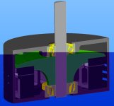
j3tch1u said:i believe there indeed would be lateral force between rotor and stator (and thus on the inner and outer bearing races). if i'm not mistaken, i read that the rotor must be very stiff and twin-rotors are sometimes used to balance out the forces. a nice angular bearing or thrust/radial combo perhaps?
Miles said:I found this today: http://alexandria.tue.nl/extra2/200111643.pdf
Miles said:j3tch1u said:i believe there indeed would be lateral force between rotor and stator (and thus on the inner and outer bearing races). if i'm not mistaken, i read that the rotor must be very stiff and twin-rotors are sometimes used to balance out the forces. a nice angular bearing or thrust/radial combo perhaps?
I assumed that the (axial) attraction between the magnets and the core would predominate, that's why I used a 40 deg. angular contact bearing at the back end and a radial bearing at the pulley end. I still think this is adequate, but I'll check it out
PS The radial bearing is a proper motor bearing, not one of those thin section jobs
Miles said:I found this today: http://alexandria.tue.nl/extra2/200111643.pdf