gfkBill
1 µW
Hi all
Just picked up for 48v 20Ah "Polinovel" battery, seems a nice unit and got a good price, but it does turn out to have a fault. Seller, to his credit, was happy to refund, but I'd like to try to fix it.
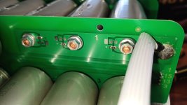
Voltage across all 15 cell groups is a nice even 3.3v, including group 1. But the BMS wiring is reading only 0.8v from 1 to 2. I suspect it's to do with the circuit board, which has a bit of extra protection, see photo. This is battery -ve end of things. Looks like a 10M resistor? No resistance between BMS connector #1 and the PCB contact pad visible below so wiring is fine. All battery groups have this circuit on their -ve end. Resistors on #1 appear practically open circuit, others all measure closed. Although voltage from 15 +ve to B- charge cable side of #1 here is 11.8V (vs ~50V at the actual #1 battery bolt), so a bit getting thru.
Previous owner was mucking about using this on a e-bike. Suspect he's blown/damaged these resistors? Are they important, or could I just short them?
(Given the history, there will be several charge/discharge cycles out on the concrete before I trust this unit!)
EDIT: Clarity


