• Hello ES! We could use some help to get us past the finish line on building the new knowledgebase for the forum.
    Can you donate? Please see our fundraising page. Thank you!

Modded Cheap Spot Welder Thread

walterwitt

New-ish here
Joined
Nov 2, 2025
Messages
29
Location
Ontario
I've been blowing up and subsequently rebuilding allot of cheap spot welder PCBs over the past few months, and now I think I've got a setup that's actually pretty robust.
2147.jpg
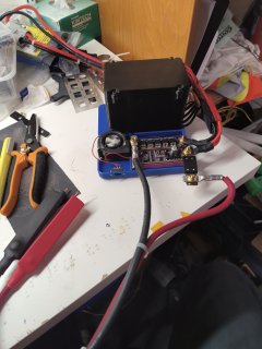
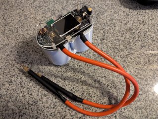
It's a 3s5p pack of pre production EVE 50PLs wired up to the cheap purple board you can get off Amazon for $25 CAD. I've doubled up the FETs with the backside footprints, reinforced all the traces with extra solder, added a cooling fan for the FETs, and made my own 6AWG spot welding probes with solid aluminum handles in heat shrink, with copper rivets as welding tips.

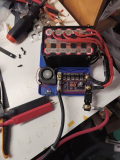
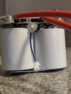
Here's a better look inside the battery
2148.jpg
I know she ain't pretty, but the welder I used to make it wasn't great, and blew up half way through it lol!

So yeah, what have you guys done to beef up these cheap spot welding boards? Also, what's your preferred power source? Li-Po? LiFePO4? Lead Acid? Supercaps?

Lets start a show and tell.
 
Depends on the version of the board but aren't the reasons these blow up due to bad driver design normally with maybe some failing from lack of voltage spike suppression? Adding more mosfets and beefing up traces is not going to solve those and will probably make it worse.

I don't recall about that specific purple board one but many of them have a pretty similar flaw where the the cap that is supposed to keep the circuit running isn't wired correctly and so when you fire a weld the voltage drops out which underdrives the FETs, increase their resistance and blowing them up. Adding more mosfets could make this worse as now you are trying to drive even more with less power to do so. There is a guy on youtube you shows how to fix many of them, normally you need to add or move a diode and resistor so the cap is wired correctly. Some also have other related design flaws where the FET driver circuit is just badly designed.

I think the other reason these can fail is because they have no voltage spike protection, no diodes, no TVS, nothing. So the FETs just have to take the voltage spike fed back into them and over time this causes them to fail. Easy enough to add a TVS though, on mine I also added some diodes but maybe not needed, a 5kw TVS will soak up a pretty serious spike.
 
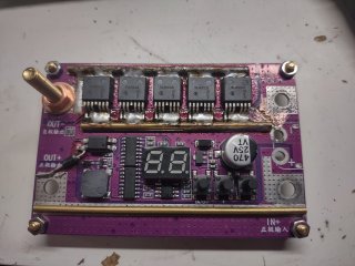
Ah yes, how could I forget the first and most important mod of all, a diode and capacitor to keep the gate drive voltage up. Here's an older photo showing it in the bottom left, along with a blown up trace on the top right.
e5330824-8de4-48cf-8df2-8f7e76695ed0-1_all_302.jpg
It's just a simple schotkey diode and 22uf ceramic cap that can handle the current/voltage spike without the need for an extra resistor.

As for a TVS, yeah, I probably should lol. I think what I'll do is prove it with my scope to see how bad the spike is and then get some through hole ones to bodge on lol.
 
Wow, your beefing up of this unit showcases some electric engineering knowhow... nice sharing that here.

I just picked up my first spot welder from BH. Its a super cap model.


I have not got to use it yet, but my first quasi mod was adding type2 silicone to a conventional cap and jumper wires that were not very secure. Trying to avoid work hardening by small vibrations through time that might lead to failure. Granted that might not be needed but if I'm moving the unit around on the workbench and such it's an easy enough preventative action.

Next step will be building some sort of base or housing that shields the unit from fingers and dust ingress as well as protecting the components. I don't have a 3d printer yet so that's going to be tricky despite there being an existing print for this model (see link). In fact, if anyone on this thread has a 3d printer and would be willing to commission a print, I'd fork $ 😊 . Color of the print doesn't matter to me, just that it's be thermally safe filament.
 

Attachments

  • 3653.jpg
    3653.jpg
    3.1 MB · Views: 5
  • PXL_20260418_120019029.jpg
    PXL_20260418_120019029.jpg
    2.2 MB · Views: 5
  • PXL_20260418_115941968.jpg
    PXL_20260418_115941968.jpg
    1.9 MB · Views: 5
There's been a few discussions recently on budget spot welders.


Ah yes, how could I forget the first and most important mod of all, a diode and capacitor to keep the gate drive voltage up. Here's an older photo showing it in the bottom left, along with a blown up trace on the top right.
View attachment 387165
That fried and cracked trace to the right of the right of the FET on main - input happened to my purple welder too.
I bridged it with some fat solid copper and kept using it.

When My Zee Lipo 3S 5.2AH failed I questioned putting any more effort into my purple welder. I figured a better Lipo would allow me to weld thicker than 0.1 copper under 0.1 nickel steel, and I wanted to put that Lipo money towards a better welder that could do 0.2+mm copper.

I didn't do the capacitor and resistor mod, instead using an xt90s on the separate 12v battery feeding the PCB to keep gate voltage high.

I have an AwithZ p20B now and have been pilfering the 8 AWG silicone wire from my purple PCB welder leads for other projects.
I had purchased a backup purple PCB expecting mosfet magic smoke but that never happened. In retrospect the money and time I spend on cheap spot welders would have been better off being spent on a better welder, and I then could have used the 0.15mm or thicker copper on my first few battery builds.

I did disable the annoyingly loud beeper on the purple welder. The automatic firing at one second nearly caused me to blow holes in cells more than once. I am strictly a pedal guy with the AwithZ
 
I bought the purple welder two years ago when I saw a youtube demo of it doing a copper sandwich, It blew up on .10 mm nickel. So did its replacement. About $36 wasted. Still using my two red welders from 2021 with the capacitor mod. Maxing out on .15mm nickel. They're sufficient for the smaller packs I may build in the future, If I were to see both fail, I'd go supercap.
 
I think you would have to be spot welding hundreds of batteries all in one go, for heat to matter. I also got this, and printed the holder in PLA.
Took your advice and printed in tPLA with an online printer for less than $30. Thanks
 
So... I was using this spot welder to make a large battery pack today, and well...
View attachment 2264.jpg
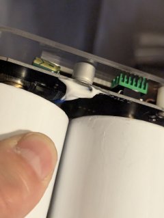
It appears I've made is so robust that instead of it blowing up, it blew a hole right through the cell. I threw this in my bucket of sand right after taking the photo as it wasn't reacting in any noticable way. Shouts out to Molicel for a safe cell design I guess.

But yeah... I think maybe I'm done frocking around with thiese cheap spot welders. I'm lucky this was the first half of the pack and I was able to remove it right away, if this was in the middle somewhere, or the other side was welded in already. And the cell didn't stay stagnant like this, I could had a missive pack fire on my hands.

So yeah, I guess maybe now this thread can be a PSA against thiese cheap spot welders. There's so much energy involved that if they glitch out and stay on, they'll ether blow themselves up, or blow open your cells.
 
Where The corner of your nickel strip would be, if it had not vaporized, is so close to the center of the blowout.

Is it not possible this hole is a result of you welding too close to the edge of the strip, or the weld probe slipped right when it fired?

I have seen people do welds at different probe distances, succesfully, often.

I try to keep the weld probes the exact distance apart on every weld , for consistency, and also avoid the edges of the strips.

If the probe distance is different each time one welds, then more or less power welding power is distributed across more or less of the strip and cell, inevitably leading to inconsistency.

I have blown holes in a cell with a cheapo black PCB spot welder. It happened when I used a pair of GC-2 Deka AGM's in series for 12v. it was like a machine gun. ratttat tatt tat, sparks everywhere. Cell was ruined but not like your blowout.

These Cheapo PCB welders need a goldilocks sized weld battery.
Not too much, not too little, and never let the probes slip into a slot or off the edge of a strip.
 
I threw this in my bucket of sand
I had not thought of this, but having it by the workbench for this type of scenario is simply brilliant. Thank you for mentioning that!

Your mention gave me a the vision to make something similar at my workstation... maybe a 5 gallon or similar sized metal bucket with a divider sheet of metal vertical inside the bucket and a handle at the top. Then, one half of the inside of the sheet split bucket is open, and the other filled with sand. When a cell or cells go thermal run away, somehow toss them into the open half of the bucket, then grab the handle and rapidly pull that sheet out to unload all that sand on top of the cell(s).

Also, bummer to hear about that welder goin haywire like this. I have not used it much, though so far my time experimenting with the super capacitor spot welder mentioned above has been a great learning experience, without any major calamity (yet). I ordered a print of the tPLA base for about $30 shipped, and its a great addon to make a steady and complete assembly.
 
Back
Top