e-beach
10 MW
So my $200 Kingpan KP3612EL 12 amp charger died after only one year. It’s a battery charger for frock-sake! It should last 10 years, but Nooooooo. 
So I hunted around and settled on this one on this eBay listed Vpower KP-669 6 amp charger advertised "for LiFePO4." It was more of an emergency buy because my bike is my main transportation and I needed a way to charge my battery pack, and the eBay price of $42.90 USA delivered to my door was attractive enough to make me hit the “pay now” button. It arrived in about 1 week, and worked as advertised in delivering 45 volts at 6 amps. . But, it turns out 45 volts may be too high a voltage to charge my Headway 40152 cells as stated in this thread.
http://endless-sphere.com/forums/viewtopic.php?f=14&t=52747
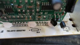
So I started thinking on how to get the voltage down so not to harm my cells. At first thought about adding 2 or 3 diodes in line on the output side figuring they have enough resistance to knock the voltage down ½ volt or so each, but then I decided that I would rather put a variable resistor in the circuit somewhere if possible to really trim this charger. The R15 seemed a perfect place to pull the 5.1k resistor and replace it with a trim pot. It was on the DC side, was metered 37.8 volts, seemed to be before the last voltage regulator or step-up coil so I decided to pull the 5.1k resistor.
 I had a Bourns 3299 10K trim pot that was in my parts box from some long forgotten project.
  The specs were superior to the 1/4 watt resistor....It worked.
http://www.mouser.com/ds/2/54/3299-61160.pdf
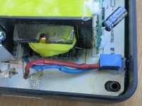
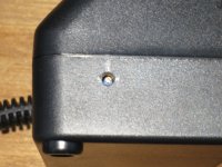
I bench tested the ohms of the removed resistor and then set the Bourns to the same ohm reading and soldered it to the bottom of the PCB. Placed into the bottom half of it's case, I then plugged the charger to my pack and once my batteries reached 44 volts, I adjusted the output to 43.8 volts. View attachment 3View attachment 2My batteries are charging happily, I get a green light when they are charged and that part makes me happy. I will change the configuration soon and will put pins through the resistor holes on the board and then solder the wires from the top. Then I will drill a small hole in the side of the charger case and hot glue the pot to the board so I can make adjustments to the output current with the case closed. View attachment 1But for now "I got a green light baby, and I got to be moving out of here." - RIP J.J. Cale 2013
[youtube]l8uk7vlk0sE[/youtube]
So I hunted around and settled on this one on this eBay listed Vpower KP-669 6 amp charger advertised "for LiFePO4."
It was more of an emergency buy because my bike is my main transportation and I needed a way to charge my battery pack, and the eBay price of $42.90 USA delivered to my door was attractive enough to make me hit the “pay now” button. It arrived in about 1 week, and worked as advertised in delivering 45 volts at 6 amps. . But, it turns out 45 volts may be too high a voltage to charge my Headway 40152 cells as stated in this thread.http://endless-sphere.com/forums/viewtopic.php?f=14&t=52747
So I started thinking on how to get the voltage down so not to harm my cells. At first thought about adding 2 or 3 diodes in line on the output side figuring they have enough resistance to knock the voltage down ½ volt or so each, but then I decided that I would rather put a variable resistor in the circuit somewhere if possible to really trim this charger. The R15 seemed a perfect place to pull the 5.1k resistor and replace it with a trim pot.
It was on the DC side, was metered 37.8 volts, seemed to be before the last voltage regulator or step-up coil so I decided to pull the 5.1k resistor. I had a Bourns 3299 10K trim pot that was in my parts box from some long forgotten project. The specs were superior to the 1/4 watt resistor....It worked. http://www.mouser.com/ds/2/54/3299-61160.pdf
I bench tested the ohms of the removed resistor and then set the Bourns to the same ohm reading and soldered it to the bottom of the PCB. Placed into the bottom half of it's case,
I then plugged the charger to my pack and once my batteries reached 44 volts, I adjusted the output to 43.8 volts. View attachment 3View attachment 2My batteries are charging happily, I get a green light when they are charged and that part makes me happy. I will change the configuration soon and will put pins through the resistor holes on the board and then solder the wires from the top. Then I will drill a small hole in the side of the charger case and hot glue the pot to the board so I can make adjustments to the output current with the case closed. View attachment 1But for now "I got a green light baby, and I got to be moving out of here." - RIP J.J. Cale 2013 [youtube]l8uk7vlk0sE[/youtube]