Mongoose DX project

I am not sure if this is the right place for this info...is there a better place to discuss HobbyCity motors?

Regarding loose magnets and Towerpro motors:
I assembled the motor after the JB Weld surface treatment and after a few minutes another magnet slipped out. Because I did not mark them I am not sure if today's event is a repeat or a new event... I did mark the errant magnet today.

I scraped off all the residual adhesive from the magnet and inside the bell and dolloped a load of JB Weld to the housing and placed the magnet. I then removed the excess and added a bit more to the very end. So this time at least this magnet should remain in place.

The Towerpro motor is running quite hot. After a few minutes of pedal starts and running up and down through the gears a few times (3 speed internal hub) to maybe 25 mph or so I pull over and put my hand on the motor - it's quite hot just about too hot to keep my hand on the motor.

It occurred to me that perhaps the thermal expansion and contraction is causing the adhesive to fail??? What do you think?
tProMotor_1.jpg
tProMotor_2.jpg

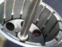
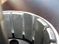
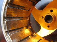
I have a Turnegy / HXT 63-74 200kv and the pics below show the way the epoxy is placed around the magnets. I have not run this motor yet - I am waiting for new bearings. The photos show that the epoxy is not placed all the way down the magnets.

HXT-63-74-200kv_1.jpg
HXT-63-74-200kv_2.jpg
If the 4 images do not display properly please give me a heads up...thanks!

How can I remove the magnets without damaging them? Sometimes I am a dumb bell :lol: - please be as specific as you can :D .
I understand that if I use CA adhesive there is a de-bonder that I can use if necessary.
Is there anything like this for epoxy or JB Weld?

Is there a recommended adhesive and process for re-gluing the magnets?

Roy
 
Roy,

Check out the pdf file I linked to in the reply right before yours. They recommend epoxy mixed with microbubbles (to thicken it).

I know a lot of people here swear by jb weld but I've had terrible luck with the stuff over the years. It just doesn't seem that strong to me. None of my experience with it applies to motors but I've always had better luck with normal epoxy. I wish I could find a high temperature epoxy locally but the one I'm trying is good to 300 degrees. Overheating may be an issue in your case though.

Now I'm wondering it it would be possible (if there's enough room with the motor assembled) to machine a thin ring of aluminum that slips over the lip of the housing to stop the magnets from moving out like that.
 
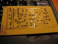
So I'm back in the States, and I had to try the magazine PCB method right away. Here's a picture of my first attempt, which isn't quite perfect:
IMG_4709_800.JPG

Version 2 will be printed with thicker traces and I'll need to find a drill bit smaller than 1/16".
From start to finish this is a pretty laborious method to make your own circuit boards, but I think the results will be worth it. Everything was done with free software: ExpressPCB and GIMP.
I just snapped screenshots of the traces in ExpressPCB resized to 300 dpi, pasted as layers in to GIMP, changed the colors, flipped one layer over and printed it out on magazine paper with a laser printer at 1200 DPI.

Here's a link to the method in case I forgot to post it previously.
 
oofnik said:
Here's a link to the method in case I forgot to post it previously.

Thanks for posting this again. I couldn't remember which thread had this link. I'm definitely going to give it a try, as it will save me a fortune in prototying boards. You don't want to know how much money I've sent to ExpressPCB in the last couple years. :roll: :mrgreen:

Question: I seem to remember something about only certain types of laser printers will work? As it turns out I'm in the market for a new printer anyway, as my Canon inkjet multi-function printer is now leaking black ink onto every page. I was thinking of getting a color laser multi-function replacement, but now want to make sure I get one that will work with this process.

Anyway, glad to see more real-world results. One tip i might mention is that as a practice, you should avoid sharp corners for traces. I put a 45-degree "bend" in at the corners.

-- Gary
 
GGoodrum said:
oofnik said:
Here's a link to the method in case I forgot to post it previously.

Thanks for posting this again. I couldn't remember which thread had this link. I'm definitely going to give it a try, as it will save me a fortune in prototying boards. You don't want to know how much money I've sent to ExpressPCB in the last couple years. :roll: :mrgreen:

Question: I seem to remember something about only certain types of laser printers will work? As it turns out I'm in the market for a new printer anyway, as my Canon inkjet multi-function printer is now leaking black ink onto every page. I was thinking of getting a color laser multi-function replacement, but now want to make sure I get one that will work with this process.

Anyway, glad to see more real-world results. One tip i might mention is that as a practice, you should avoid sharp corners for traces. I put a 45-degree "bend" in at the corners.

-- Gary

Here's my results for using this. I went to Kinko's and bought the thin glossy "magazine-like" paper that you can buy individually. I know, I can try individual pieces of magazine paper just lying around, but some experienced folks suggested existing ink on the page can be problem as it can cause bridging so I'd thought I'd just try blank sheets. They cost 41 cents each, for me, although I've heard they've cost 5 cents to others on the net. Maybe Seattle is just more expensive? Oh well, it beat the $1.some-odd-amount I'd have to pay for special PCB paper on the net.

Results:

10-mil traces imprinted just fine. They were nice and solid.

Anything at or less than 10-mil spacing was iffy - mostly successful, but the failure rate was too high (like 40%). I'd suggest 15-mil spacing as a minimum if you want a greater-than-98% success rate.

And, make sure the pads are relatively generous (So your drilling isn't that bad), and make sure the inner hole isn't the tiniest possible. This method likes to smear a tiny bit, shrinking a few holes in the process.

So, in essence, for prototyping, the method works great. But I'd have a hard time recommending it for production. If you want precision, I would definitely prefer the UV method, though that's obviously more expensive.
 
More good info, thanks.I usually do 20-mill traces anyway, just because anything less is just too hard for my tired old eyes to see clearly without an electron microscope. :roll:

Even if I had to pay $20 a sheet for special thin paper, it would still be a ton cheaper than what i'm doing now. If I do a new board through ExpressPCB, the minimum order is two boards. Since there is a per order setup fee of $55, it makes each of those two boards anywhere from $40-$50 each. That is too painful to justify in my head, so what I usually do is order four boards, thinking if the board design doesn't need rework, I can then have three "production" boards. What happens everytime, though, is I use one out of the four boards, and the rest go to my every growing pile of useless boards. :oops:

The types of boards I usually do are a bit too complex to "breadboard", so mostly it is easier to just get the boards laid out, and then get some made. What I really need to do, which this process will be perfect for, is to add a step to prototype parts of the design, and get it working first. Right now I'm in the throes of trying to do something I'm calling a "CMS Lite", which is basically just the shunt portion of the BMS circuit, pus some extra logic to use a red-green LED in each channel, with no charger control section. I've done two version s of this design, and only populated a couple channels worth, on two of the 8 boards I got made, each designed for 16 channels. I still don't have the circuit completely right, so I need a new version. If I use this approach, I can just do a small prototype board, with a couple channels, and repeat as necessary. :D Once I get it right, I can still use ExpressPCB for the production, which is quite reasonable, for higher quantity production runs.

BTW, is there anything special about your Laser printer?

-- Gary
 
RWP said:
How can I remove the magnets without damaging them? Sometimes I am a dumb bell :lol: - please be as specific as you can :D .
I understand that if I use CA adhesive there is a de-bonder that I can use if necessary.
Is there anything like this for epoxy or JB Weld?

Roy

I just saw your question. Maybe this is not too late to help. Here is a link I have bookmarked about ungluing magnets. I have never tried it.
http://www.rcgroups.com/forums/showthread.php?t=976471

Bubba
 
Back
Top