Motor perhaps overextended?

Cyclomania

10 kW
Joined
May 22, 2022
Messages
715
Location
Northern Europe
I have a bike with a 250 watt motor.

I have overvolted this bike quite a lot. So I have a controller with max current of 25. And a 48volt battery 17AH.

When going up a slope earlier today. The motor then started making all kinds of strange noises. At least I am 80% sure this sound comes from the motor.

The battery connections still shows me 48 volts so I don't think the battery or controller have taken any damage. But the motor gave me a lot of strange sounds. It still runs but with a strange sound. Any idea what this is or how I can fix it?
 
I bought a T100 and grabbed YouTube videos. A horticultural guy with zero electronics skills and with the right tool, well, Bobs your uncle.
 
I bought a TS100 and grabbed YouTube videos. A horticultural guy with zero electronics skills and with the right tool, well, Bobs your uncle. MINIWARE Mini Electric Soldering Iron Kit TS100, Output Power 24W-65W, Adjustable Temperature 100℃-400℃, Programmable, OLED Display, Powered by DC5525 with Wall Charger/Car Charger/Power Bank https://a.co/d/5KHHkh0
 
E-driver_ said:
Can you guys also explain why this type of soldering that I have done will melt when I put great current through it? While a solder from a bigger iron, like the one above, won't melt from a large amount of current? I mean it is still the same tin. So can someone explain why it won't melt when it is done with an iron like the one above?
Not specifically because of the soldering iron you used (although that is likely part of the problem), but because the solder joint is poor in terms of electrical current handling capability.

As I noted earlier:
Solder (I think you are calling this "tin?") is not as electrically conductive as copper.
Copper is highly electrically conductive. Solder is much less electrically conductive.
High electrical conductivity is the same as low resistance, and vice-versa.
Passing high current (high amperage) thru a low electrically conductive (high resistance) material generates heat.

As I also noted earlier:
The best solder joints have large portions of both mating surfaces touching and spread out along each other. (The two highly electrically conductive materials are touching each other maximally.) This minimizes the generation of heat.
If the two mating surfaces are separated by a large blob of solder in between, the current has to pass thru the low electrically conductive (high resistance) solder blob to get to the other side. With higher currents (amps) it can get hot enough to melt the solder and/or any components (in your case, wire and connector) close to it.

Have you studied any YT soldering tutorial videos yet? :wink:

Here are some more helpful reading materials:

https://endless-sphere.com/forums/viewtopic.php?t=47203

https://www.bestrobotics.org/site/survival_guide/education_resources/sasoldering.html

https://mightyohm.com/blog/2011/04/soldering-is-easy-comic-book/

Here is one to help with your XT connector:

https://oscarliang.com/soldering-guide/#xt60
 
99t4 said:
Solder (I think you are calling this "tin?") is not as electrically conductive as copper.
Copper is highly electrically conductive. Solder is much less electrically conductive.
High electrical conductivity is the same as low resistance, and vice-versa.
Passing high current (high amperage) thru a low electrically conductive (high resistance) material generates heat.

Yes but I think these connections are normally fastened through tin/solder. So should it just be a smaller blob or what is the main issue? Since these are normally connected with solder I mean.
Should the solder be smaller or what is the main problem of this specific blob? This is what I don't understand.

I understand the cable should go through the holes. That makes sense. But why is a big solder bad? And a small solder good ? I don't quite understand what the alternative is. Smaller solder or tighter solder?

I realise mine is not good. But I want a constructive solution and alternative. If A is bad I want to know what alternative B looks like :)

I am watching those videos yeah.
 
Solder is not nearly as effective electrically or mechanically as copper wire. Basically, a soldered joint should be a good tight secure fit between the wire and the tab, post or whatever, plus solder flowed over and into it. The solder serves as adhesive and sealant; it should not be used as a conductive element of the main circuit.
 
E-driver_ said:
I understand the cable should go through the holes. That makes sense. But why is a big solder bad? And a small solder good ? I don't quite understand what the alternative is. Smaller solder or tighter solder?

I realise mine is not good. But I want a constructive solution and alternative. If A is bad I want to know what alternative B looks like :)
I rebuilt one of those packs that had a bad connector. It had shorted out and melted the plastic. I just drilled a hole in the end of the case and used a cable with an XT60 connector that I plugged in. Simple solution that works. If I were to do it again then I would use a set of 30 Amp Anderson power pole connectors. That also allows one to place a power meter in line with the battery on occasions.

99t4 and Chalo are correct. Mechanical (in this case 'crimp') copper to copper connections are more reliable, have less resistance, waste less energy (electrically more efficient).
 
LewTwo said:
E-driver_ said:
I understand the cable should go through the holes. That makes sense. But why is a big solder bad? And a small solder good ? I don't quite understand what the alternative is. Smaller solder or tighter solder?

I realise mine is not good. But I want a constructive solution and alternative. If A is bad I want to know what alternative B looks like :)
I rebuilt one of those packs that had a bad connector. It had shorted out and melted the plastic. I just drilled a hole in the end of the case and used a cable with an XT60 connector that I plugged in. Simple solution that works.

Hmm you drilled a hole in the actual battery you mean? So the connection from the battery was also an xt60-connection? Instead of pins?
 
Chalo said:
Solder is not nearly as effective electrically or mechanically as copper wire. Basically, a soldered joint should be a good tight secure fit between the wire and the tab, post or whatever, plus solder flowed over and into it. The solder serves as adhesive and sealant; it should not be used as a conductive element of the main circuit.

Aha so in my case I should basically put the cable-wire through the holes so they are touching? Then I can solder the whole thing?

But perhaps this is doable with my small solder station? The other one that was suggested to me here is from Amazon so that one has to wait a while.
 
E-driver_ said:
Hmm you drilled a hole in the actual battery you mean? So the connection from the battery was also an xt60-connection? Instead of pins?
Yes, I drilled a hole in the plastic case of the battery (not the mounting block) and ran the black and red power cables out of the battery. Then I terminated them with the XT60 connector.

That dinky little solder station you are talking about is designed for working on small electronics and circuit boards. It is NOT intended for use on heavy gauge power cables. Get a proper soldering iron or use crimp connectors.
 
LewTwo said:
E-driver_ said:
Hmm you drilled a hole in the actual battery you mean? So the connection from the battery was also an xt60-connection? Instead of pins?
Yes, I drilled a hole in the plastic case of the battery (not the mounting block) and ran the black and red power cables out of the battery. Then I terminated them with the XT60 connector.

You basically took the red and black out of the hole in the battery and soldered them with an xt60? I see.

This would eliminate this problem I guess. Good to know that is doable for another time as well.
 
E-driver_ said:
Crimp connectors could be used for connecting the cables to the pins on the battery rail?

Sort of like these crimp connectors?

https://www.aliexpress.com/item/1005003374713632.html?spm=a2g0o.cart.0.0.42b838daHxypYv&mp=1
Take a look at the wire sizes (they do not show a DC current rating) ...
H7f848fcd891946759cd056f6e96e00baP.jpg


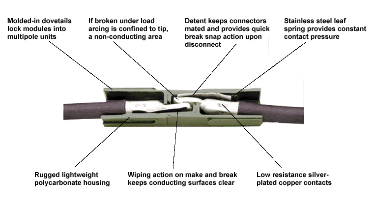
You might be able to get by with the first ones but I really meant crimp connectors like these:

powerpole_cutaway.gif


file.php


https://www.amazon.com/dp/B07BRBRZ86
 
LewTwo said:
E-driver_ said:
Crimp connectors could be used for connecting the cables to the pins on the battery rail?

Sort of like these crimp connectors?

https://www.aliexpress.com/item/1005003374713632.html?spm=a2g0o.cart.0.0.42b838daHxypYv&mp=1
Take a look at the wire sizes (they do not show a DC current rating) ...
H7f848fcd891946759cd056f6e96e00baP.jpg


You might be able to get by with the first ones but I really meant crimp connectors like these:

powerpole_cutaway.gif


file.php


https://www.amazon.com/dp/B07BRBRZ86

Nice.
 
So I have tried a thing.

And now I don't think it is the soldering giving rise to the issue anymore. It is probably a very bad solder.

But the issue with the cutoff arises also when I am using another battery. I have now switched to another battery rail and battery. And this issue still arises.

It cuts off at times. Which is strange. Looks like the video below. And also there are two connections. Perhaps the fact that there are two connections might give rise to this problem as Chalo talked about. Perhaps the connections are no good?

https://www.veed.io/view/726e3368-f618-4174-8ecd-39674a7ce31e?panel=share
 

Attachments

  • Skärmavbild 2022-12-16 kl. 22.03.37.png
    Skärmavbild 2022-12-16 kl. 22.03.37.png
    1.7 MB · Views: 224
  • Skärmavbild 2022-12-16 kl. 22.03.31.png
    Skärmavbild 2022-12-16 kl. 22.03.31.png
    1.3 MB · Views: 224
If your new controller is drawing more current than your battery is capable of supporting, then either individual cells or the whole pack could be sagging enough to trip the BMS's low voltage cutoff. And if you try another pack with the same limitation, it will happen to that pack too.
 
Chalo said:
If your new controller is drawing more current than your battery is capable of supporting, then either individual cells or the whole pack could be sagging enough to trip the BMS's low voltage cutoff. And if you try another pack with the same limitation, it will happen to that pack too.

Yeah but the thing is I have the same battery on another bike and controller that draws basically the same wattage going hard uphill (I think). At least that one seems to go up to about 11-1200 watts on the display when I am pushing it

So is that not a bit strange?

Hmm in that case I guess I will have to wait until I have built my 52 volt battery with 60a BMS later this winter. And try that one on.
 
I now have one of those soldering stations from Amazon that E-HP among others thought was good.

Why was it again that this bigger soldering iron was better? Because it melts more surface area or something?

Looks like below:
 

Attachments

  • Skärmavbild 2022-12-31 kl. 15.28.08.png
    Skärmavbild 2022-12-31 kl. 15.28.08.png
    1.4 MB · Views: 113
So the last few days I have switched the battery rack/rail to a new one which came with the cable already soldered on. So this one I did not solder on, so it should work fine.

I also have a shorter extension cable between the battery cable and controller cable which is 10awg and more robust. The battery is the same.

But.. this issue with the cutoffs still arises. I don't know why.

I am going to do the test of the droppage tomorrow, with the amperege-tester connected between the extension cables, to see what happens when the cutoffs occurs.

I don't know if this tells us anything but what I did notice today, on the display, is that the wattage drops when the cutoffs occurs.

I was riding up the same steep hill multiple times. When the battery was fully charged and had been inside in the warmth, the first time I rode down the hill, and then up again. Nothing happened this first time. But I don't know if that was just a coincidence.

The second time I rode up the hill and the charge had dropped, perhaps from 100% to 96% or something like that, I noticed the first small cutoffs.

Third time I noticed more of them and the fourth time about the same amount of cutoffs as the third ride.

When I went up the hill the first time the wattage, on the display showed around 1280-1290 when it was working at the steepest and hardest.

Second and third time I had around 1270-1230 perhaps. Fourth time I rode up the long hill around 1200-1190.

I do notice that the wattage drops when the cutoffs occurs on the display. Drops from around 1200 to sometimes just a little bit. To 1100. Sometimes a lot more it seems.

It is cold outside now so perhaps that plays a role? Around 8 minus-celsius when I was biking. So perhaps in the beginning when the battery was warm and charged up it did not happen because of this?

But despite the cold I did notice that the battery was quite warm from all the stress when I went inside again. I also have a cover over it in this cold. So perhaps the cold is not the reason ?

I am quite perplexed. Do you think it is somewhere in the cables or something that this occurs? BMS doing the cutoffs? Or what could be the reason.
 
E-driver_ said:
Can you guys also explain why this type of soldering that I have done will melt when I put great current through it? While a solder from a bigger iron, like the one above, won't melt from a large amount of current? I mean it is still the same tin. So can someone explain why it won't melt when it is done with an iron like the one above?

Is it plugged in? You should just practice soldering until you get better at it. You heat conductors/connectors that you're soldering using the iron, and apply the solder to the joint between heated conductors/connectors. You don't run current through the solder (It's confusing when you use random electrical terms in your descriptions).
 
E-driver_ said:
I now have one of those soldering stations from Amazon that E-HP among others thought was good.

Why was it again that this bigger soldering iron was better? Because it melts more surface area or something?

Looks like below:
Rather than retype it, you can read it
https://endless-sphere.com/forums/viewtopic.php?f=49&t=117956&start=100#p1742451

The tip of that soldering iron holds so much heat, that I could unplug it, and it still would have enough heat to solder one or two more XT150 connector afterwards.
 
Yeah great. I am going to fix that one also with this new soldering iron in time.

But I have a working battery rail now. So my questions are more regarding that the cutoffs still occurs, as I wrote in my last post.

The soldering was probably not the issue, although I greatly appreciate the facts about the new iron so I can make a better soldered connection for the other rail in the future.

But the issue still arises, as I wrote in my last post, despite a factory-produced new battery rail. I don't understand why it arises. I see watts dropping on the display when it occurs. But I don't know if it is because of some bad wiring somewhere inside the battery perhaps(?), bms could be the problem? Or if the cold does this or why this is happening.
 
E-driver_ said:
Yeah great. I am going to fix that one also with this new soldering iron in time.

But I have a working battery rail now. So my questions are more regarding that the cutoffs still occurs, as I wrote in my last post.

The soldering was probably not the issue, although I greatly appreciate the facts about the new iron so I can make a better soldered connection for the other rail in the future.

But the issue still arises, as I wrote in my last post, despite a factory-produced new battery rail. I don't understand why it arises. I see watts dropping on the display when it occurs. But I don't know if it is because of some bad wiring somewhere inside the battery perhaps(?), bms could be the problem? Or if the cold does this or why this is happening.


Well I can't help, but I'd like to learn something new. What is a battery rail exactly?
 
E-HP said:
E-driver_ said:
Yeah great. I am going to fix that one also with this new soldering iron in time.

But I have a working battery rail now. So my questions are more regarding that the cutoffs still occurs, as I wrote in my last post.

The soldering was probably not the issue, although I greatly appreciate the facts about the new iron so I can make a better soldered connection for the other rail in the future.

But the issue still arises, as I wrote in my last post, despite a factory-produced new battery rail. I don't understand why it arises. I see watts dropping on the display when it occurs. But I don't know if it is because of some bad wiring somewhere inside the battery perhaps(?), bms could be the problem? Or if the cold does this or why this is happening.


Well I can't help, but I'd like to learn something new. What is a battery rail exactly?

I don't know if this is the right word for it in english. Since I am not english or american. But I mean the thing that the battery is connected to on the bike. I've seen this word on Aliekspress for it. Battery rail.

When you take of the battery it is not connected to the battery rail. When it is on the bike it is connected to the rail.

The rail is always on the bike. And has the cable going to the controller.
 
Back
Top