Motorcycle class Hub Motor

Mark,
Well done, and I'm very excited about the opportunity to purchase one (or more ;) of these when you're ready to sell. I'm actually re-designing my current conversion to utilize this motor....

One suggestion about the brake disk. If I may suggest, find an 'off the shelf' popular disk, such as from a GSXR, CPR, Ninja, etc, and design the mounting to support that disk. You may want to go with a front disk, as rears may be too small (I'm not too up on current sportbike disk diameters, but I'm sure others are). This way, those of us who want a rear disk (that includes me) can go with a OEM part, aftermarket, etc, from many manufactures, and it would give you a "standard" solution that most people could adapt to... Some may need something special, of course, but at least it would give you a baseline offering.... You might want to do the same for the sprocket side as well....

And about rims, I laced on a couple of Excel rims on my old honda 550 from Buchanon Spokes, an was VERY happy with the products and service. No personal connection with the company, but I was impressed.

http://www.buchananspokes.net

Just my 2 cents, very excited about this solution!!!!!!

Thanks,
Glen
 
The rear brake on a motorcycle (at least in all my motorcycles), gets very little wear. I've been through a couple rotors and few sets of front pads on my GSXR1000, and I'm still on the stock rear break disk and pad, and they still look fairly new. My GSXR-750 and R6 were the same way. Remember, on a motorcycle, when you brake, your rear tire just lifts up anyways. I use it on my dirtbike to get the tire to slide in tight technical stuff, and I use it to hold in place at stoplights, but that's about it. I would imagine any rear rotor would last a very long time (at least with my riding style).


Engine oil passages often use a neat trick for getting fluid passages where they need them through long paths of aluminum. You drill a straight passage, then tap the ends of the passage, and thread in plugs with loctite into the ends of that passage. Then you drill a hole in from the side to intercept that passage, and thread in a nipple fitting, or feed whatever you needed to supply oil to. For example, you could drill 2 holes all the way through the aluminum of this hub, then plug them with flush mounted plugs so it doesn't effect the mounting in the rear wheel stays. Then drill in from a location that is friendly to your bike's wheel stay design, and thread in small nipples wherever needed. I think it would be nice to just connect the passages on one side, then run the in-out lines on the same side together. A cheapy in-tank fuel pump (go for a carb pump, not an injection pressure pump) sitting in a small reservoir tank would be fine for circulation. Just have the return water passage flow through a small heater core on it's path back to spill into the reservior tank. That would only take perhaps $30bucks at a wrecking yard for the parts, $20 in fittings and hose from a hardware store, and perhaps 2-4hrs of time of easy drilling, tapping, threading and mounting some parts. Then my friend John could relax his cooling concerns :)
 
Well I just want to say everyone following this thread knows I'm not selling anything or even quoted a price until I'm happy with the design. This thread has been going on for a long time and repeatedly I've been asked when am I going to sell the 602 and time and time again I've said when I'm finished with testing and happy with the design.

Saying that I am rushing this product to market is a joke and being talked down to and pressured into doing something I'm not confortable with and would add months more to the design cycle when design, manufacturing and testing time is figured.

It is precisely the fact that I have not finished testing that I am not selling yet. But next week if all goes well with the new stator testing; the wait will be over and I'll quote a price and lead time for the wheel.
Just to restate if testing goes well if not; well I won't sell what I'm not happy with.

Mark
 
Mark, Thanks for the advice on the dual controllers... Feel free to e-mail me anytime about the lacing of the "new hub". I usually us Buchanans spokes and rims for a quality job. You can also order the individual piece parts by giving them the hub hole diameter, number of spokes, and lacing style (cross 2 etc.). "Brit" wheels usually use 40 spokes while others use 36 spokes. Regards
John Head
Elegant British Bike Bits.
 
I have a question Mark.

I noticed that the motor uses the laminations layed up on an angle to reduce the cogging feel at the expense of efficiency. It appears that they may have used the same angle used by a regular X-lite hub stator? Now, when you double the width of the stator, this doubles the number of radial degrees of stator lamination shifting, yet it uses the same number of magnets on the same diameter ring, correct? If the lamination overlap pushes beyond the width of a single magnet, then your motor will have efficiency reduced quite a bit, as it will have part of it fighting itself.

Maybe it has all ready been considdered, but definately something to look into improving if they just layed up twice the amount of laminations over the same jig used for making a regular 50x series hub motor stator.

Best Wishes,
-Luke
 
From looking at this photo,

file.php


it would appear that the laminations go quite a bit past the neutral overlap area (to make a cog-free feeling motor), and into an area that will cause a decrease in torque and efficiency. You may wish to tell them to make a new jig to stack the stators on, if the width is double, you would want it to use half the angle, or even less to increase efficency further.
 
liveforphysics said:
From looking at this photo,

file.php


it would appear that the laminations go quite a bit past the neutral overlap area (to make a cog-free feeling motor), and into an area that will cause a decrease in torque and efficiency. You may wish to tell them to make a new jig to stack the stators on, if the width is double, you would want it to use half the angle, or even less to increase efficency further.

Wow thank you I will look into this. Man this is the kind of help that makes this place so great. When I have the stator out I will measure the width of the magnets in relationship to the angle of the laminations. I know with the old stator, which uses the same angle there is fair amount of low end cogging. these are the things I can get correct easly.

Again thanks

Mark
 
liveforphysics said:
From looking at this photo,

file.php


it would appear that the laminations go quite a bit past the neutral overlap area (to make a cog-free feeling motor), and into an area that will cause a decrease in torque and efficiency. You may wish to tell them to make a new jig to stack the stators on, if the width is double, you would want it to use half the angle, or even less to increase efficency further.

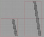
So on examination of magnet to slot angle all seems fine. below is a drawing showing the relationship of slot angel to the magnets. This is the same relationship on all Xlyte motors

Mark
 

Attachments

  • magnet to slot angle.jpg
    magnet to slot angle.jpg
    26.3 KB · Views: 2,280
Are you sure about that my friend?

Here is an X5

file.php
 
If we could get a photo from a better angle, it would be a simple matter to compare. From peeking at a funny angle, it would appear that the laminations go well past 1 slot of radial twist that they do in the X5. Sometimes looking at things from angles can trick the eyes, so perhaps I'm way off.
 
liveforphysics said:
If we could get a photo from a better angle, it would be a simple matter to compare. From peeking at a funny angle, it would appear that the laminations go well past 1 slot of radial twist that they do in the X5. Sometimes looking at things from angles can trick the eyes, so perhaps I'm way off.

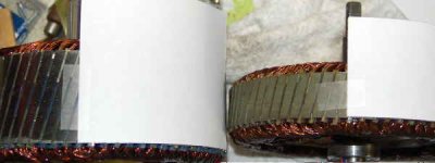
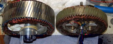
OK here is the direct compassion and yes the 2 stators use about the same angle so the 602 overlaps more than the 502 how this effect efficiency VS acceptable cogging I don't know but I will explore this. Since there is substantial low end cogging I am not sure I would want to make it worse unless there was alot to be gained.

Thanks for the tip definitly worth exploring
New Stator goes in today so my current focus is to not lose a finger
She sure is a big stator compared to the X5

Mark
 

Attachments

  • measure_1_S.jpg
    measure_1_S.jpg
    12.5 KB · Views: 2,178
  • Big boy and baby.jpg
    Big boy and baby.jpg
    31.1 KB · Views: 2,178
  • magnet to slot angle_2.jpg
    magnet to slot angle_2.jpg
    53.7 KB · Views: 882
I like the solid aluminum web connecting the stator to the shaft. It should allow water cooling the axle to remove a lot of heat.

Did the ID of the stator laminations get smaller with the deeper slots? If the Iron under the stator teeth is too thin and saturates, a lot more of the AC flux in the core will leak out and cause eddy currents in the die-cast aluminum support. I picked up this particular tidbit reading the web-sites of some RC motor builders.

I've played with the demo version of MagNet from Infolytica. This software does FEA solutions of electo-magnetic field problems. It's fairly easy to learn. (i.e. basic knowledge of EM fields, electro-magnetic material properties, and the help file are enough) I used it to play with a fancy permanent magnet configuration. FEA tools can provide detailed performance information on a part/assembly before it's physically made. Even so, FEA suffers from the same problems as any other simulation. I.e. if the input or the simulation is garbage, the output is also garbage. (i.e. check your work and assumptions u lazy bum! :lol: )

Still has ten fingers,
Lawson
 
lawsonuw said:
I like the solid aluminum web connecting the stator to the shaft. It should allow water cooling the axle to remove a lot of heat.

Did the ID of the stator laminations get smaller with the deeper slots? If the Iron under the stator teeth is too thin and saturates, a lot more of the AC flux in the core will leak out and cause eddy currents in the die-cast aluminum support. I picked up this particular tidbit reading the web-sites of some RC motor builders.

I've played with the demo version of MagNet from Infolytica. This software does FEA solutions of electo-magnetic field problems. It's fairly easy to learn. (i.e. basic knowledge of EM fields, electro-magnetic material properties, and the help file are enough) I used it to play with a fancy permanent magnet configuration. FEA tools can provide detailed performance information on a part/assembly before it's physically made. Even so, FEA suffers from the same problems as any other simulation. I.e. if the input or the simulation is garbage, the output is also garbage. (i.e. check your work and assumptions u lazy bum! :lol: )

Still has ten fingers,
Lawson

I questioned the issue of saturation of the core and I have access to and know people who know FEA. We did a quick assessment on the flux at practical current levels. My experience and the people I work with have extensive experience in the design of electromagnets for MRI systems, so I know materials but not motor exactly. I spent a few year in my youth rewinding AC motors while in school. So I know or understand winding a motor and drive systems.

You can do a google patent search of my name an get a sense for my experience.
here you go

http://www.google.com/patents?q=mark+gelbien ... ch+Patents

You can be confortable that I'm reviewing the design, though I can miss something since I'm only human and help is always welcome. Though I am uncomfortable with negative speculation, why not positive speculation after all its just speculation. If there is a satuation problem I'll see a big increase in current with no real increase in performance.
Mark
 
All the theorizing and speculation on possible issues is fine, but what I'm waiting for is for this beast to be hooked up and taken for a "spin". :wink: I know what an x5 will do. It will let my Toenie cruiser bike have accelerations like a motorcycle. I'm guessing this will do the same in a "real" motorcycle. I'm not planning on entering the Isle of Man race ( :mrgreen: ), so I don't need to go a 100+ mph. I just want somethig that can handle freeway speeds, occasionally, and has "typical" ICE motorcycle-like acceleration, and from what my rather generous gut tells me, this should do fine on both counts. What really makes this motor attractive for me is that unlike many here, I don't have the equipment or the skillsets required to do the custom motor mount fabrication required to replace an ICE setup, so this super-sized hubmotor setup makes a conversion possible for me. I'm guessing there are others in the same boat.

Anyway, I'm in "line" for one of these, and will be sending Mark a PayPal payment, just as soon as he tells us the price. The sooner he quits taking pictures, and gets this all buttoned up and installed on his bike, the better, as far as I'm concerned. :)

-- Gary
 
markcycle said:
You can be confortable that I'm reviewing the design, though I can miss something since I'm only human and help is always welcome. Though I am uncomfortable with negative speculation, why not positive speculation after all its just speculation. If there is a satuation problem I'll see a big increase in current with no real increase in performance.
Mark

Aw, don't take it personally Mark, I imagine it gets hard to hear but I don't see it as any reflection on you or what you are developing. I'd take it as flattery - people looking for improvements just means they are buying into your vision. You are in a community of tweakers and people are just trying to lend a hand as best as they know how. You know we'll all want to buy one when they are out!

You are doing something revolutionary by making a more powerful hub motor that is accessible to the masses, and except for that one funny guy who prefers stinkpots and tricycles we are all stunned by your progress.

-JD
 
Bottom line: best product idea for repowing I have seen. I can't wait to try one.

Sold my KLR650 last year and this is exactly the sort of approach that will make e-cycles home buildable. I'm keeping an eye out for a 250-350 dual purpose frame, because having the space for lithium pack where the motor would go is key.

Cuttting edge! Awesome :mrgreen:
 
Mark, thank you for the great pictures.

To the best of my knowledge, to have a neutral feeling pull with minimal cogging, a setup with a twist of 1 slot/arm width is ideal. More than this amount of radial offset will either require the timing interval to be shortened up a lot (less power/torque), or if the controller is kept the same and the slot twist is increased, during the rotation, part of the pole will be fighting (canceling) torque production. I think the cogging effect you feel is caused by the leading edge of the pole going into the opposite polarity magnet before having the field switched. This would cause pulsations in torque output, as well as having a negative effect on efficiency and power.

I am not an expert, but I do remember learning that exceeding 1 slot/arm of radial twist was a big "no-no" when building a motor. However, my application was brushed perm-mag DC motors with much fewer poles, so different rules may apply with high pole count BLDCPM motors. If indeed it could achieve greater optimization by decreasing the angle, it should be a very simple matter for the factory to setup a jig with less angle when stacking laminations.

When you release these, I'm strongly considdering picking a pair of them up to build a pair of e-bikes for my parents with them. I think it's a great idea, and i love the silence and simplicity it will provide. I also think it's great you want to personally test and run them through the gauntlet before you release the product. Your openess shows great integrity.

Best Wishes,
-Luke
 
lawsonuw said:
Mark, sorry if I ruffled your feathers a bit. Hard to tell how much experience someone has over then net. From the looks of those patents, this was a case of the EM field n00b (me) "informing" the guru how to get things done. :oops:

Anywho, that is still a great looking motor!

Lawson

No I'm no Guru at best I just work hard and when that's not enough I seek help and when that's not enough I just try to test the hell out of the design, then redesign and redesign again. Then if I'm lucky it'll work well.

Mark
 
I think your approach is often the best way Mark. Lots of respect.

-Luke
 
GGoodrum said:
Anyway, I'm in "line" for one of these, and will be sending Mark a PayPal payment, just as soon as he tells us the price. The sooner he quits taking pictures, and gets this all buttoned up and installed on his bike, the better, as far as I'm concerned. :)
-- Gary

Gotta agree with Gary on this one Mark. Your motor is EXACTLY what many people here are looking for, so how about that price and ETA? Ball park for the moment would suit me. Are we talking AGNI or ETEK territory here?

Andy.
 
evmotorcycle.org said:
GGoodrum said:
Anyway, I'm in "line" for one of these, and will be sending Mark a PayPal payment, just as soon as he tells us the price. The sooner he quits taking pictures, and gets this all buttoned up and installed on his bike, the better, as far as I'm concerned. :)
-- Gary

Gotta agree with Gary on this one Mark. Your motor is EXACTLY what many people here are looking for, so how about that price and ETA? Ball park for the moment would suit me. Are we talking AGNI or ETEK territory here?

Andy.

OK tell ya what for those interested in the MHM602-HP wheel, lets try to tally up who would want a 17 X2.15 rim, 18 X 2.15, just motor or a custom rim spoked to the hub.

Cost - It will close if not the same or a little more as a Angi motor, but and here is the big thing no chain or sprockets to buy and all that related hardware and welding.

You will get a completed wheel cross 2 spokes if possible, definitely on 17 and 18 inch rims, custom torque arm (send me pictures of the bike) free interface plate for a Disc rotor (Disc rotor not included in price) and free tech support for the wheel and also free support on the complete electrical system for basically for as long as you use the wheel.

One more side benefit the first batch of motor I order will have machined side covers (not casted) If you want a collectors series motor so to speak (not really) then this is your chance after this I hope to be going to castings. Also this first shipment is coming to me by air shipping and all the related added expense that brings.

If you want to start out slow (speed wise) then I can offer a 18 fet 72 volt controller set for 80 amps battery current. The Kelly is my controller of choice.

Full spec's will be on my web page if my daughter ever finishes it.

Lead time about 4 weeks, could be quicker but this is what I'll quote right now.


Two things are stopping me from taking deposits right now

1) I haven't finished the testing of this new stator yet
2) My daughter hasn't finished my E-comerence web page yet, she promised me by the end of the weekend.

I hope this helps and gives everyone more to think about.

Rim size needed or I know I'll order all the wheels with the wrong rims.

Mark
 
Thanks, Mark. I don't yet have a donor bike, but I'm looking, so I guess I'm open as to what size rim to get. Which do you think is more popular? I'm afraid I don't what most motorcycles use. I know there's probably lots of factors and lots of choices, but i'm not sure what I need. If it is more related to the style of bike, like an enduro-style, or one of the "crotch rocket" types, I can say it won't be the latter. :) I won't be doing any road racing, or trail riding, I just want a fairly lightweight "street bike". I will fill every nook and cranny with as many a123 cells as I can get to fit, mainly to get as much range as I can. I already have plenty of ebikes that will get me around town. What I need is something to get between towns. :) Actually, what I want is to go from my house, which is in Orange County, down to our condo in San Diego, which is about 50 miles, pretty much all freeway (I5...).

Anyway, I'll try and check out what is the more common size for the style of donor bike I'm looking at.

-- Gary
 
Having also built Hobby Brushless DC motors, I too believe that the angle of the stators on that prototype motor is off considerably. It makes zero sense to have one stator overlapping 2 others! If it the video has a stator like that one, then we're going to have one high performance motor once the stator is corrected.

Mark: I'd be interested in either the 17 or 18" versions. I don't have a donor bike yet, so don't know exactly which one I'd buy. However if the cost is competitive with the Angi, I'll be in for at least one. Thanks very much for the ballpark numbers, that helps me a lot!

-Jim
 
kingjamez said:
Having also built Hobby Brushless DC motors, I too believe that the angle of the stators on that prototype motor is off considerably. It makes zero sense to have one stator overlapping 2 others! If it the video has a stator like that one, then we're going to have one high performance motor once the stator is corrected.

Mark: I'd be interested in either the 17 or 18" versions. I don't have a donor bike yet, so don't know exactly which one I'd buy. However if the cost is competitive with the Angi, I'll be in for at least one. Thanks very much for the ballpark numbers, that helps me a lot!

-Jim

You guys are right about the angle I got to thank you all for the tip. I am so focused on the interface of the wheel to the bike and just assumed Xlyte knew how to make a motor that I didn't think to study the stator in that much detail in fact until I got the new stator I hadn't seen a stator for the 602 separated from the rotor.
Thanks Luke and Jim and others for the heads up.

Mark
 
Back
Top