
Several people have asked about how i did this, its no secret i just have not got around to doing an explanation but as today is a national holiday in the UK and it is raining i have found the time.
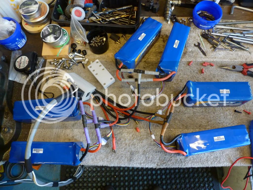
The system is made of 6 6s zippy 8ah packs, these are permanently parralelled at cell level into 3 pairs of 2 packs, that is the main power leads and the balance port leads are permanently connected.
The change over device has 2 plugs either of which can be plugged into the socket on the bike, one of these plugs is to ride the bike and connects the 3 parralelled pairs in series and connects them to the controller so the bike is running on a 18s2p pack, the other plug is on the end of the charger cable and connects the 3 pairs in parrlel as a 6s6p pack so that it can be charged by my 6s 306b icharger.
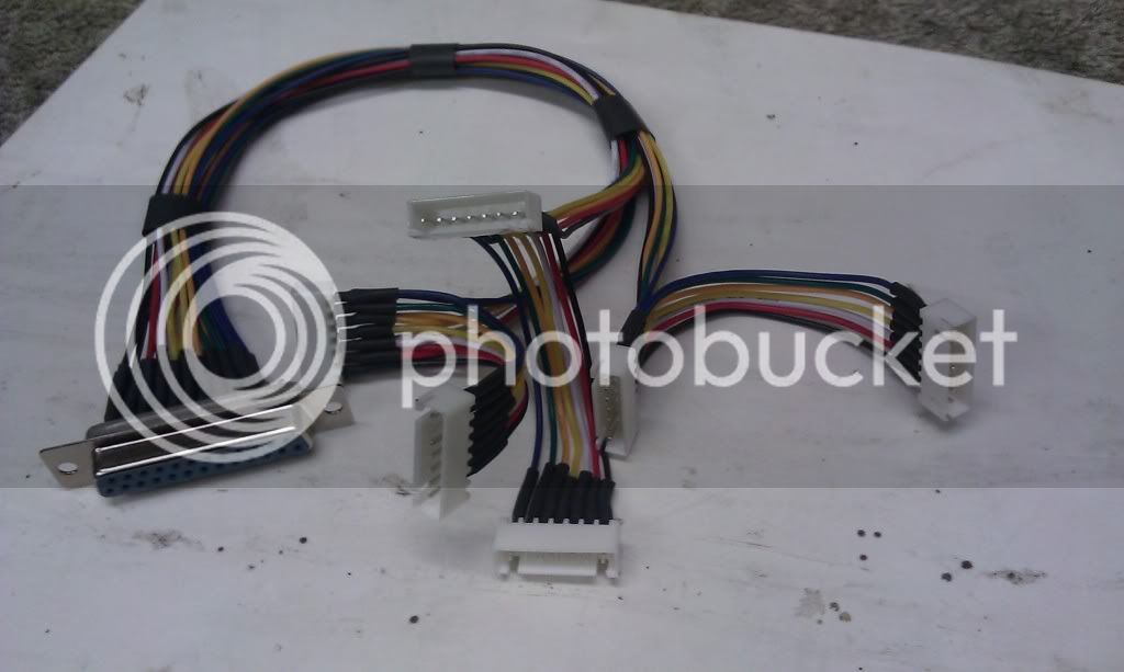
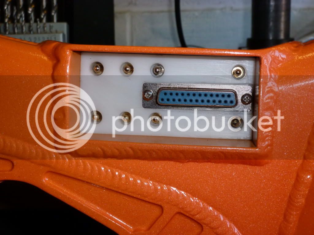
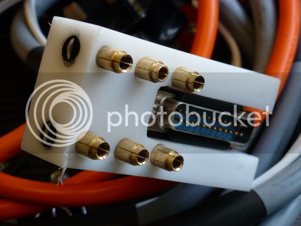
The balance leads from the 3 permanently parralelled pairs are all fed into a 25 pin d-sub connecter in the bike mounted socket, the individual wires are arranged as folows, pin 1,2 and 3 are the first wire from each pair, pins 4,5 and 6 are the second wire from each pair etc untill all the 7 wires from each balance cable is connected into the d-sub, this does leave 4 spare pins which could be used for a temp sensor in the pack so the charger can monitor the pack temps during charging.
The other part of the d-sub is on the end of the charger lead with pins 1,2 and 3 connected together terminating in a single wire, so are pins 4,5 and 6 etc, this results in 7 wires which go into the 6s balance port on the charger.
When the Bike run plug is removed the 18s2p pack is broken down into 3 6s2p groups and isolated from the controller, the charge plug connects these up as a 6s6p pack and connects the balance wires all together resulting in 6x 6p cell strings, the icharger can display the individual 6p cell string voltages, on initial connection of the charger any out of balance readings would indicate a problematic cell which would require the pack to be broken down further to identify the rogue cell, this has never happened, all the cells have remained perfectly balanced, probably helped by balance charging every time i charge.
I dont know how people create those fancy schematic diagrams so please excuse my drawn ones, if some one wants to reproduce these nice and fancy go ahead!
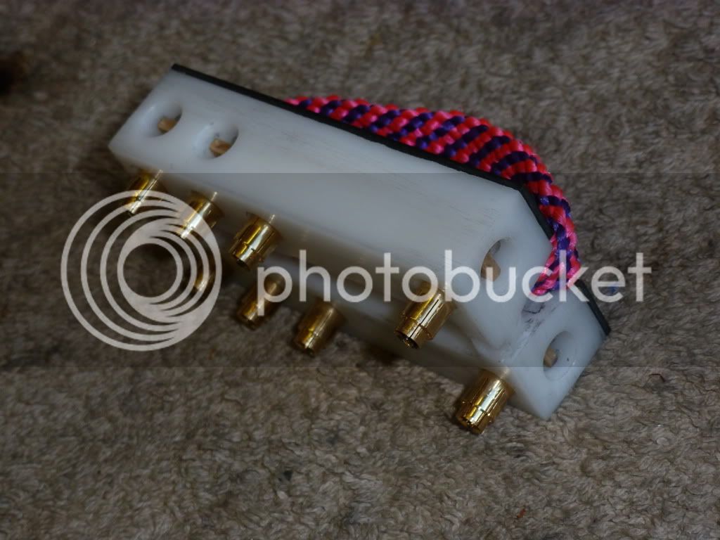
The balance lead loom and connectors;
The pack assembled on the bench;
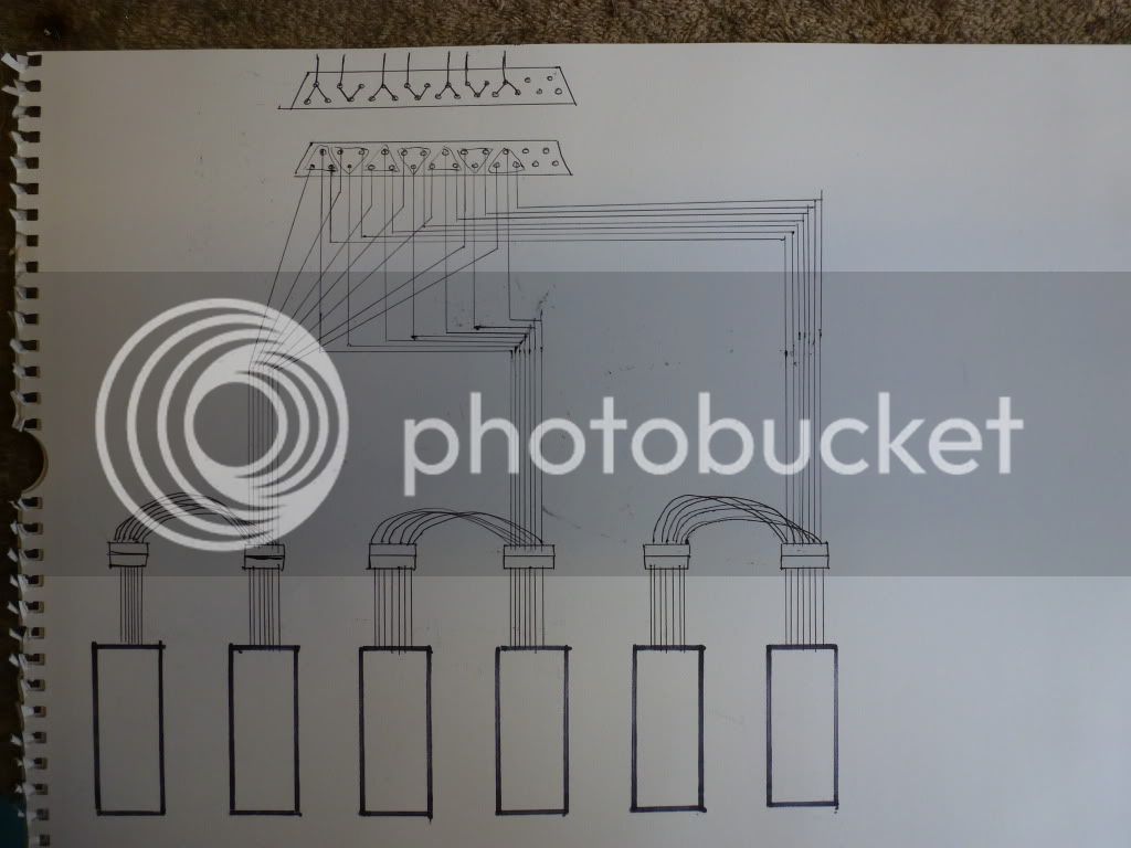
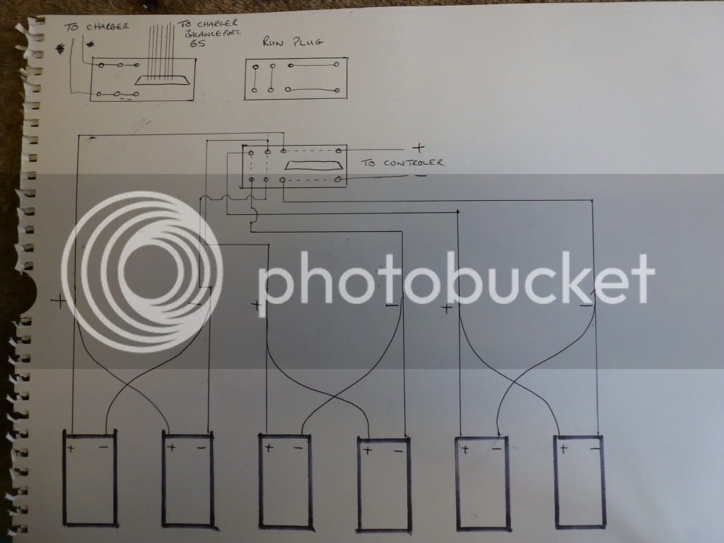
This is a drawing of how the balance leads are connected;
The socket on the bike;
The run plug, this has the bridges between the connectors arranged as shown by the dotted lines in the drawing below.
The charging plug;
I am sure my description will be lacking in some way so if you have any queries ask away,
Also, please get a good grasp and understanding of the principles involved here before you attempt to do something like this, the consequences of a wrong connection could be catastrophic!! Expensive, dangerous or both!!
Simon.
The system is made of 6 6s zippy 8ah packs, these are permanently parralelled at cell level into 3 pairs of 2 packs, that is the main power leads and the balance port leads are permanently connected.
The change over device has 2 plugs either of which can be plugged into the socket on the bike, one of these plugs is to ride the bike and connects the 3 parralelled pairs in series and connects them to the controller so the bike is running on a 18s2p pack, the other plug is on the end of the charger cable and connects the 3 pairs in parrlel as a 6s6p pack so that it can be charged by my 6s 306b icharger.
The balance leads from the 3 permanently parralelled pairs are all fed into a 25 pin d-sub connecter in the bike mounted socket, the individual wires are arranged as folows, pin 1,2 and 3 are the first wire from each pair, pins 4,5 and 6 are the second wire from each pair etc untill all the 7 wires from each balance cable is connected into the d-sub, this does leave 4 spare pins which could be used for a temp sensor in the pack so the charger can monitor the pack temps during charging.
The other part of the d-sub is on the end of the charger lead with pins 1,2 and 3 connected together terminating in a single wire, so are pins 4,5 and 6 etc, this results in 7 wires which go into the 6s balance port on the charger.
When the Bike run plug is removed the 18s2p pack is broken down into 3 6s2p groups and isolated from the controller, the charge plug connects these up as a 6s6p pack and connects the balance wires all together resulting in 6x 6p cell strings, the icharger can display the individual 6p cell string voltages, on initial connection of the charger any out of balance readings would indicate a problematic cell which would require the pack to be broken down further to identify the rogue cell, this has never happened, all the cells have remained perfectly balanced, probably helped by balance charging every time i charge.
I dont know how people create those fancy schematic diagrams so please excuse my drawn ones, if some one wants to reproduce these nice and fancy go ahead!
The balance lead loom and connectors;
The pack assembled on the bench;
This is a drawing of how the balance leads are connected;
The socket on the bike;
The run plug, this has the bridges between the connectors arranged as shown by the dotted lines in the drawing below.
The charging plug;
I am sure my description will be lacking in some way so if you have any queries ask away,
Also, please get a good grasp and understanding of the principles involved here before you attempt to do something like this, the consequences of a wrong connection could be catastrophic!! Expensive, dangerous or both!!
Simon.
