
You are using an out of date browser. It may not display this or other websites correctly.
You should upgrade or use an alternative browser.
You should upgrade or use an alternative browser.
N.E.S.E. the no solder module
- Thread starter agniusm
- Start date
There are so many variations of xPyS layouts and shape/size constraints, it would be pretty impractical to try to accommodate them all in the way (I think) you're asking.Hickbeard said:Have you thought about a single version for x amount of series groups.
Terminology:
A group is cells connected in parallel, as each module is here.
Those groups are then connected in series, which creates a "string" of groups.
And some people connect "modules" of strings in parallel to flexibly allow for different capacity packs.
With higher capacity cells, sometimes a string is composed of single cells directly rather than groups.
agniusm
1 MW
Hickbeard said:Have you thought about a single version for x amount of series groups. Would it be strong enough. It would save a lot of space and some weight.
A single case still utilising the tab set would be pretty cool.
Sent from my CLT-L09 using Tapatalk
This was the idea when i started working on this, make 36v and 48V complete kits. While still working on the kit i came up with module idea and trashed complete sets right away as like john61ct wrote, there are too many variations and this product is oriented to diy so broad choice to make a battery was priority. I probably would not get third of the orders i have now.
Space is an issue but its to the point. No one builds 200km bikes, maybe few exeptions and for the wast majority for battery people need the size comes out not too bad.
spinningmagnets
100 TW
Cells can be at wildly different voltages, but you can connect them in series with no concern. For instance, a 36V pack and a 48V pack in series makes a 23S / 84V pack.
However, when you connect them in parallel, they need to be very close in voltage (I use 0.10V as my default when assembling a pack).
This is why I like the NESE modules, they are paralleling cells. A 6P module of 3400-mAh cells (6P x 3.7V x 3.4-Ah) is only 76 watt-hours, which is below the 100-WH transportation limit.
As a callback to past threads, this is what I meant by "parallel first", coming from an insulated-wire background.spinningmagnets said:Cells can be at wildly different voltages, but you can connect them in series with no concern. For instance, a 36V pack and a 48V pack in series makes a 23S / 84V pack.
…
This is why I like the NESE modules, they are paralleling cells.
I've since learned that guideline is not quite as critical when spot-welding packs using nickel-strips, since the serial connections between groups are overlaid right on top, pretty much "parallel & serial at the same time".
I think it was you pointed out that going string-first may be better than group-first, lowering resistance for the higher currents in high-power scenarios?
Hence my query above about letting the user choose / change the xPyS layout rather than locking it into the hardware design.
spinningmagnets
100 TW
Yes, that was me. For low-amp packs, it really doesn't matter, but when drawing high amps from a pack, every layer of nickel you add to the path of the current is a "resistor".
In a common 14S pack where the series buses are added first (and then parallel on top of that), there are only twelve 0.20mm thick nickel layers between the 14 cell groups. So, 12 X 0.20mm is 2.4mm thick of nickel. If you add the parelleling strips first, you have added another 2.4mm of nickel that the current must pass through to go from the negative electrode, through the controller and motor, back to the positive electrode. 2.4mm of nickel, vs 4.8mm of nickel.
Either configuration will equalize all the cells in parallel just fine, in fact...the added resistance to the parallel path is a good thing. When pulling common performance from common cells, one layer of nickel is just fine, and it spot-welds very easily and reliably. For high amps, one layer of nickel is a resistor, and using two layers of nickel is not the optimal choice. Using 0.20mm copper for the series current is four times better.
ZeroEm
1 MW
Well said "spinningmagnets" now it clicks for me long mains and parallel to it. I have been watching these modules. Want to make custom batteries for my trike to run along the frame on each side. 20S4P X 2.
agniusm
1 MW
Good thing this system uses 0.6mm and 1mm copper. Its hard to get same throughoutput with nickel and spotwelding
Frank
100 W
Please excuse my ignorance about these smaller batteries, but does this design accommodate any/all brands? I guess I don't understand if there's small differences between different manufacturers' offerings which might influence how they fit in the holder. I need to make a replacement pack for my e-bicycle but all my experience is with large packs.
Thanks for any advice.
Thanks for any advice.
Frank
100 W
Specifically I'm wondering about button-top versus flat-top; do they both work?
spinningmagnets
100 TW
Do not buy button-top cells, they are slightly longer, plus they have a resistor built-in...you need the "flat top" cells.
https://www.electricbike.com/inside-18650-cell/
https://www.electricbike.com/inside-18650-cell/
Frank
100 W
Great info - thanks for the link. I'm leaning towards the 21700 format at this point and like the granularity of the smaller cells.
agniusm
1 MW
30% OFF, code: smallisbig
on small 2P and 3P (including 2S2P, 2S3P) modules, also hardware kits (manual discount, refund after order)
on small 2P and 3P (including 2S2P, 2S3P) modules, also hardware kits (manual discount, refund after order)
will_newton
1 kW
I have an ebike that needs a new battery. I have a 3d printer. I have been wanting to make a round cell pack vs. pouch. Sooooo, I just placed an order for hardware.
Plan is for a simple 12s8p 18650 pack. It will be replacing a 2x6s 16000mah HK lipo pack. The NESE pack will be split into two 6s packs for charging/balancing on a Hyperion Duo r/c charger, same as I do with the HK lipos.
It should be a fun project.
Plan is for a simple 12s8p 18650 pack. It will be replacing a 2x6s 16000mah HK lipo pack. The NESE pack will be split into two 6s packs for charging/balancing on a Hyperion Duo r/c charger, same as I do with the HK lipos.
It should be a fun project.
will_newton
1 kW
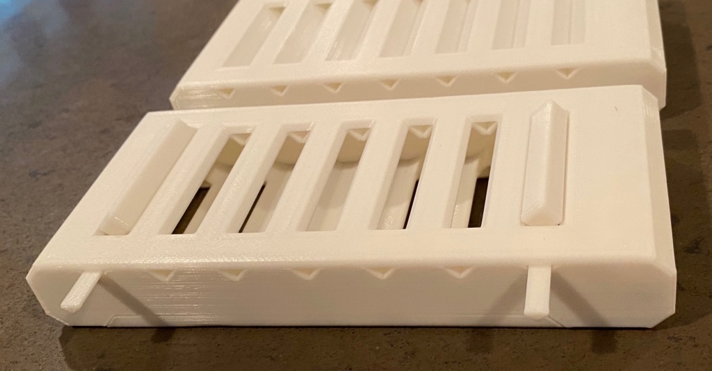
While waiting for stuff to arrive, I designed a couple of alignment pins and blocks for the 18650 size holders. Fits vented or closed style.
Files available here:
https://www.thingiverse.com/thing:4378125
Files available here:
https://www.thingiverse.com/thing:4378125
akbarramzan
10 µW
- Joined
- Jun 2, 2020
- Messages
- 5
Hey, I received my order but I do not know how to get the 30% discount for the hardware kit?
This is my paypal invoice id: AT-4215
This is my paypal invoice id: AT-4215
akbarramzan
10 µW
- Joined
- Jun 2, 2020
- Messages
- 5
Ah shizzle nvm, I thought you mean 2P and 3P modules + any hardware kits
agniusm
1 MW
Probably better to make 21P by paralleling 3 modules. So yes, its simple. I had one pack die cause of my stupidity, 20S7P, and it took me 3 hours to replace the cells and be back running.samv76 said:hmm this looks interesting. im looking to replace my 20S20P battery pack in my govecs.
can a similar pack, or even better 21S20P be made with this solution? and yes, how?
Adamshmadam
10 µW
A lot of information there I just want to buy them how do I do that
agniusm
1 MW
Some news.
18650(20.5mm vs 22mm V1) and 21700(23.5mm vs 26mm V1) V2 is finished. 26650 is also done and die with first batch will be ordered soon.
Good news is that 18650 and 21700 will share old 18650 series bus bars. 26650 will have their own.
18650/21700 bus bars are ordered and in the making so its not long till i have them in stock again.
I have started working on Makita tool battery. The design will use original Makita lid but will take 2 to 8 cells and will be rebuildable many many times. It will use ultra thin modules at 18.5mm.
So far the design is made for older style PCB's without management but i will get the new ones done as well. I am still early in this and its a teaser, nothing more, but its good to share stuff with people to get some opinion.
Sure it will be larger than original but its rebuildable many times and some tools like lawn mowers dont mind that. 6 to 24AH Makita battery would be dope") Oh, and it should use original charger too.
Oh, and it should use original charger too.
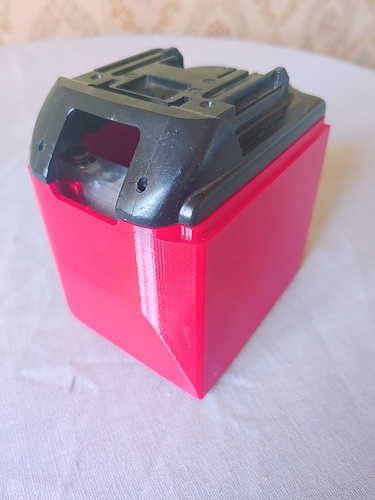
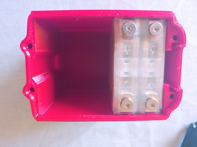
This is 4P(12ah)
I am offering 35% discount for complete modules till old stock lasts. Contact me if you are interested.
18650(20.5mm vs 22mm V1) and 21700(23.5mm vs 26mm V1) V2 is finished. 26650 is also done and die with first batch will be ordered soon.
Good news is that 18650 and 21700 will share old 18650 series bus bars. 26650 will have their own.
18650/21700 bus bars are ordered and in the making so its not long till i have them in stock again.
I have started working on Makita tool battery. The design will use original Makita lid but will take 2 to 8 cells and will be rebuildable many many times. It will use ultra thin modules at 18.5mm.
So far the design is made for older style PCB's without management but i will get the new ones done as well. I am still early in this and its a teaser, nothing more, but its good to share stuff with people to get some opinion.
Sure it will be larger than original but its rebuildable many times and some tools like lawn mowers dont mind that. 6 to 24AH Makita battery would be dope
Oh, and it should use original charger too.
This is 4P(12ah)
I am offering 35% discount for complete modules till old stock lasts. Contact me if you are interested.
district9prawn
1 kW
That makita pack looks nice!
I have not checked in on this thread for some months now. Great to see so many new projects and improvements.
What good cells are there in the 26650 format?
I have not checked in on this thread for some months now. Great to see so many new projects and improvements.
What good cells are there in the 26650 format?
agniusm
1 MW
Thanks. One good cell is A123 2.5ah iron phosphate if you dont mind the weight and lower wh/l.district9prawn said:That makita pack looks nice!
I have not checked in on this thread for some months now. Great to see so many new projects and improvements.
What good cells are there in the 26650 format?
My brain says dont do it but my heart shouts go fir it
. I know there is little demand on these cells but it makes a nice set of most commonly used cells.Similar threads
- Replies
- 14
- Views
- 874
- Replies
- 11
- Views
- 585
- Replies
- 3
- Views
- 937
- Replies
- 3
- Views
- 1,137