Need help identifying LVC resistors on my controller

Joined
Feb 28, 2024
Messages
3
Location
Germany
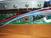
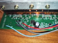
I want to change the LVC from 52V to 44V but i can't find the voltage divider, maybe someone has some information on this controller?
IMG_20250122_154627.jpg
 

Attachments

  • IMG_20250122_154351.jpg
    IMG_20250122_154351.jpg
    4 MB · Views: 12
  • IMG_20250122_154243.jpg
    IMG_20250122_154243.jpg
    4 MB · Views: 8
  • IMG_20250122_154142.jpg
    IMG_20250122_154142.jpg
    3.7 MB · Views: 6
  • IMG_20250122_154156.jpg
    IMG_20250122_154156.jpg
    3.9 MB · Views: 4
  • IMG_20250122_154204.jpg
    IMG_20250122_154204.jpg
    3.4 MB · Views: 3
  • IMG_20250122_154215.jpg
    IMG_20250122_154215.jpg
    3.8 MB · Views: 4
  • IMG_20250122_154227.jpg
    IMG_20250122_154227.jpg
    3.7 MB · Views: 2
  • IMG_20250122_154238.jpg
    IMG_20250122_154238.jpg
    4.2 MB · Views: 4
  • IMG_20250122_154327.jpg
    IMG_20250122_154327.jpg
    4.3 MB · Views: 6
  • IMG_20250122_154334.jpg
    IMG_20250122_154334.jpg
    4 MB · Views: 9
It's very likely to be right up near the MCU itself, with some op-amp or other buffer chip between it and the MCU if it's designed safely, directly to an MCU analog input pin if not.

Some put the divider and buffer near the wire that powers on the controller when connected to the battery voltage wires.
 
It's a tedious detective search. First identify all the resistors that have one end connected to the positive controller lead. Then identify all the resistors that have one end connected to ground. You make a list or mark the ends with red and green magic marker, Then probe with a continuity meter between the free ends of all these resistors. At least one pair will connect. That coukd be the voltage divider stack, but there might be others,

It needs to reduce the battery voltage down to something under the microcontroller power supply, which is 3.3 or 5 volts, so expect at least a 10:1 divider, maybe 14:1.

.
 
Thank you for the suggestions, i'll look into it a little bit deeper on the weekend. I have a feeling that the TP358 op-amp goes directly to the mcu.
 

Attachments

  • ic.jpg
    ic.jpg
    4.3 MB · Views: 2
It's a tedious detective search. First identify all the resistors that have one end connected to the positive controller lead. Then identify all the resistors that have one end connected to ground. You make a list or mark the ends with red and green magic marker, Then probe with a continuity meter between the free ends of all these resistors. At least one pair will connect. That coukd be the voltage divider stack, but there might be others,

It needs to reduce the battery voltage down to something under the microcontroller power supply, which is 3.3 or 5 volts, so expect at least a 10:1 divider, maybe 14:1.

.
Do dual voltage controllers have two voltage dividers or one for the LVCs?
 
Do dual voltage controllers have two voltage dividers or one for the LVCs?
I only have seen the reverse engineered schematic for the KT S06 controller, and it shows one divider. I suspect most of these simpler controllers sprung out of the same original design. They all seem to power up in the same fashion,

You got a microcontroller running the board. It can power up and determine the battery voltage. Then it uses that knowledge to pick the right LVC and store it in a register. With a KT controller, some of their displays can rewrite that register to adjust LVC per the L parameters,
 
Just a update, if someone needs to change the LVC on this Tongli Controller i got in contact with the manufacturer and they told me what to change. It is R234 on my board and i changed it to a 11k resistor and now it works great.
 

Attachments

  • mmexport1742533782065.jpg
    mmexport1742533782065.jpg
    901.1 KB · Views: 2
Last edited:
Back
Top