Need to put an Ump in my BMC

Jonathan

10 W
Joined
Apr 16, 2008
Messages
69
Guys, I got myself an EVTech BMC motor. The motor is very well built with plenty of torque.
But running stock @ 36V there's just not enough at the high end. Top speed is less than 20 mph.

Is there something I can do to get into the 30mph range. I heard that the clyte controller 36-72V no longer works with these after the digital upgrade (what ever that means).

Is there another brushless controller out there that can take it up to the +50V range?

Thanks
 
You could search for one of the older Crystalyte controllers or possibly look into a Kelly controller.

I still don't understand why the newer V.2 controllers have a problem with BMC and Puma motors.
It might be something to do with the pull-up resistors on the hall sensor signals.
 
I also recently purchased a BMC motor and had an email discussion with Justin at ebikes.ca.

He had this to say "there is an upper commutation frequency limit on the Crystalyte digital controller, so at some speed with your PUMA hub it will cease to work correctly."

He did mention that they should have more of the analog 24-48V 35A controllers in the next shipment which wouldn't have this limitation, but that if you need to use it with more than a 48V nominal (60V max) battery pack then you'd have to replace the mosfets.
 
Hi

Is this a stamped BMC motor? does it have the logo on the case of the motor? you should get more than 20mph in a 26 inch wheel at 36V? 24mph is the norm, yes the problem with the new xlyte controllers is indeed the com speed, you could try a Kelly controller or just wait for the analogue controllers to come in, it may be worth giving Bob Mcree a call as he may have a spare kicking around, dont falcoln ev still stock the controllers?

Knoxie
 
Roonster said:
I also recently purchased a BMC motor and had an email discussion with Justin at ebikes.ca.

He had this to say "there is an upper commutation frequency limit on the Crystalyte digital controller, so at some speed with your PUMA hub it will cease to work correctly."

Hmm... interesting.
In testing the Puma motor, which is essentially the same as the BMC, I noticed the hall signals had a somewhat slow rise time.

With the old "analog" Crystalyte controller, the halls were fed a higher voltage which allows for a faster rise. I believe the newer V2 only uses 5v.

The observation that there is a upper frequency limit would be consistent with a slow rise time.

Once you exceed this "limit", the hall timing will be out of sync and things will start blowing up.

Fortunately, there is an easy fix for this. Add pull up resistors between the hall supply and the three hall signal wires. Not sure what value would be optimal, but the SS41 hall sensors have something like 4.7k internal ones, and that is not low enough. 1k might load down the supply too much, but that would be within the rating. 2.2k should be a good comprimise.
 
This is a stamped BMC with the sticker indicating 250W.

This morning I charged up all the batteries, check the tire pressure, and mount my TomTom GPS and took it out for a ride.
On the flat it took ~150 yard to get up to 16 mph then slowly creeped up to 20 mph after about a full block of road. I then turned around did the same ride in reverse to make sure there's no hill affect, same results.

So my top speed is 20 mph according to my GPS. @ max speed I can still out pedal the motor.

The total weight of bike & rider is 222 lbs if that makes any difference.
 
There might be a way to increase the power on your existing controller.
I'm not sure we know what's inside that one. Is it possible to see what FETs and caps it has?
 
it may be worth giving Bob Mcree a call as he may have a spare kicking around

Last I heard from him, he was backed up pretty deep in work, between the BMS project and real life.

Jonathan, Rooney, what is this with the changing names on the forums? :roll:
 
The BMC 25A controller does have FET/cap/resistor. However, it's potted. I'm currently looking for a clean way to remove the potting.
When I do I'll post the pictures.

Laz, Jonathan = PerplexArt and that's it. I like my real name and been using it through the many forum. When I signed up I accidentally click on the under 18. anyway long story short. I'm using Jonathan from now on.

As for Roony, he's someone else who is going thru the same process of wanting a BMC/Puma configuration. I think!
 
Jonathan said:
Laz, Jonathan = PerplexArt and that's it. I like my real name and been using it through the many forum. When I signed up I accidentally click on the under 18. anyway long story short. I'm using Jonathan from now on.

As for Roony, he's someone else who is going thru the same process of wanting a BMC/Puma configuration. I think!

Oh, "Roonster" is "rooney2", from whom I bought my controller (thanks again!), since he ordered ebikes.ca's last 4110 unit and found it wouldn't work with his BMC. Or, at least I assume it is him, given the similarity in name, that he's setting up a BMC, and having troubles with finding a controller, and that he discussed the v1 analog units with ebikes.ca. Could all be a coincidence. :wink:
 
Mkay, Jonathan, this is what I mentioned on the phone:

http://cgi.ebay.com/48V-600W-brushless-controller-for-E-bike-scooter_W0QQitemZ260222524177QQihZ016QQcategoryZ11332QQcmdZViewItemQQ_trksidZp1742.m153.l1262

Note the inflated shipping price. Still, it's a pretty good deal. Some folks here have had success with it, unmodified, at some decent voltages.

http://endless-sphere.com/forums/viewtopic.php?f=8&t=2615&st=0&sk=t&sd=a&start=45
 
No coincidence Laz, One in the same. Still waiting to see you get the new controller up and running :mrgreen:

Jonathon, I'm seeing around the same speed as you are with the BMC stock setup on a 36V15AH Ping battery.
 
Oh, it runs! Just got it running this afternoon. I have some kinks, though, especially with weight distribution. The darn thing's a bucking bronco!

Anyway, Roonster, what're you using to control your BMC?
 
fetcher regards resistors to speed up the hall sensors,
you mean basically puting resistors in parallel with the hall sensors, i.e. from red to each colour ( except black) ?, to lower its internal resistance?
Would puting a higher voltage to the hall sensor also work? do you know voltage the analogs are giving to halls? 12v?
this would be extremely interesting if it solves the problem
 
solarbbq2003 said:
fetcher regards resistors to speed up the hall sensors,
you mean basically puting resistors in parallel with the hall sensors, i.e. from red to each colour ( except black) ?, to lower its internal resistance?
Would puting a higher voltage to the hall sensor also work? do you know voltage the analogs are giving to halls? 12v?
this would be extremely interesting if it solves the problem

Right. Something like 1k or 2.2k. It appears the controller already has a 2.2k.
If you increase the hall supply voltage, you'd have to clamp the outputs with diodes or something so the input to the microprocessor does not exceed 5v. The analog controller feeds the halls from a ~12v supply through a resistor. When operating, the halls are running around 7-8v.

That ecrazyman controller off eBay might work. I don't know anyone who has tried one with a BMC.

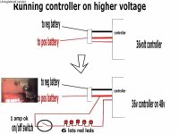
If the original controller is potted, I would not recommend digging it out, since there is a good chance of damaging something. If the original controller has a separate wire to switch it on (other than the main battery wires), you could try putting a big 12v zener in series with it and try 48v. If the controller blows up, then dig the potting out. Most commonly used FETs are rated for at least 60v.
 
If the original controller has a separate wire to switch it on (other than the main battery wires), you could try putting a big 12v zener in series with it and try 48v.

Oh, you lost me there. Darnit, and I thought I was getting good at this...
 
On most controllers, the main battery wires go straight to the main caps and FETs. The control logic runs off a voltage regulator, which is typically fed by a smaller wire through the on / off switch. By putting a 12v zener in series with this wire, you drop the 48v down to 36v to keep the voltage regulator happy. The right value of resistor would work too. Current in this wire is ususally under 100ma.

Not all controllers are wired in this manner, but most are.
 
using 12v zener diode to drop voltage by 12v, do you put the diode in with positive end as normal or does it need to be reversed? i.e. is pic attached correct?
 
Looks right except the zener looks backwards. The banded end should go toward the battery (usually).
 
thanks fechter
another pic, I tried same with 6 red leds, works a treat, also makes a nice 'on' light, drops down near enough to 12v, have noticed a few different 36v controllers using LM317T or similar, so probably running near max voltage of regulator, wouldn't hurt to put an led or two on the on/off wire, also nice way to know if controller is on.
 
Has there been any progress on this project? I'm curious to know as I'm thinking about a BMC and I'm trying to figure out what controller I'd want to run. I really like the specs of the Kelly (KBS72051) controller, so I'm curious to know if anyone has found something else that works with BMC? Did the higher voltage add speed to your setup, or do you think you're already at too high of frequency for the controller?

E.
 
The e-crazyman controller works perfectly with my BMC.
 
Back
Top