New alleged Panasonic battery failed to deliver in road test

eTrike said:
Hi John, that's a nice result! Another very rough calc shows ~85% of your resistance is IR.

Looking forward to an ugly pic if you'd care to share ;)

Hey thanks

Yeah Im pretty happy...but tell me how did you calculate the IR of the pack? (not that I dont believe you as that seems about right...)


I cant post a pic at the moment as the pack is foam and shrink wrapped...

John
 
2thin strips to handle 60A, all I can say about that is lol.
That pack was very poorly built by someone with no clue whatsoever.

Depending on how thick those strips are, it's only a question of less or more wrong.
A nickel strip of for example 8mm x 0,15mm will only be good for 4-6amps with conservative values.
And if its steel you do the math.

I am glad it didn't short on the cells where the shrink melted.
 
Wheazel said:
2thin strips to handle 60A, all I can say about that is lol.
That pack was very poorly built by someone with no clue whatsoever.

Depending on how thick those strips are, it's only a question of less or more wrong.
A nickel strip of for example 8mm x 0,15mm will only be good for 4-6amps with conservative values.
And if its steel you do the math.

I am glad it didn't short on the cells where the shrink melted.

No clue?...Well, your WRONG about that one. It wasnt poorly built either. There always has to be one..For your information, I built another 72 volt pack and when I took it apart it shows NO SIGNS what soever of over heating and that controller pulls a max of 29 amps. Once I balance it I will test this with my bike limiting the amps to 29 and see what the voltage sag and resistance values are.

I think you might be laughing at yourself, as in parallel the 8 group of cells act as one and they share the brunt of 55 amp load; that is each cell is pulling about 7 amps each and that is spread over all of the nickle strip. Clearly after only putting one more strip on the series connections the resistance went down almost 200 ohms and when I took it apart no sigh of overheating. After that I simply attempted to reduce the resistance untill it is where it is now at about 180 ohms.

People do make mistakes, but as long as you correct them your ok, but assuming then because of a mistake the person knows nothing is assuming wrong.

John
 
eTrike said:
johnnyz said:
but tell me how did you calculate the IR of the pack? (not that I dont believe you as that seems about right...)
Hey I goofed and used the wrong datasheet(GA not NCRB), but I usually get info from lygte-info.dk.
I estimate IR using the graph @50% SOC, from there calc 8x in parallel, then x24 for series. My numbers aren't adding up on this one, probably due to SOC and temp. Scratch previous estimate :?
Either way, I don't think you could ask for a better result-- nearly half of your previous best :D Thanks for sharing!

Thanks , I appreciate that...mistakes can be made but as long as one learns from them....and I dont think I can do much better with these particular cells. Next build will be a 10 amp cell.

John
 
johnnyz said:
Wheazel said:
2thin strips to handle 60A, all I can say about that is lol.
That pack was very poorly built by someone with no clue whatsoever.

Depending on how thick those strips are, it's only a question of less or more wrong.
A nickel strip of for example 8mm x 0,15mm will only be good for 4-6amps with conservative values.
And if its steel you do the math.

I am glad it didn't short on the cells where the shrink melted.

No clue?...Well, your WRONG about that one. It wasnt poorly built either. There always has to be one..For your information, I built another 72 volt pack and when I took it apart it shows NO SIGNS what soever of over heating and that controller pulls a max of 29 amps. Once I balance it I will test this with my bike limiting the amps to 29 and see what the voltage sag and resistance values are.

I think you might be laughing at yourself, as in parallel the 8 group of cells act as one and they share the brunt of 55 amp load; that is each cell is pulling about 7 amps each and that is spread over all of the nickle strip. Clearly after only putting one more strip on the series connections the resistance went down almost 200 ohms and when I took it apart no sigh of overheating. After that I simply attempted to reduce the resistance untill it is where it is now at about 180 ohms.

People do make mistakes, but as long as you correct them your ok, but assuming then because of a mistake the person knows nothing is assuming wrong.

John

Yes there is a lot of strip where its dead weight and very little strip/conductor where the current has to pass. There will be next to none current in the parallel connections if the pack design is good to start with. (taken the cells are good quality and consistent) It doesn't matter is you connect 100cells in parallel, the current still has to pass to the next series group, and that connection has to handle the full current of the pack. Hence why people that know about I=U/R would choose another layout/better series connections. And more clueless people come and tell you that the series connections are no issue when you have showed a pic of blue-burnt series connections.
 
So you are saying that the parallel connections carry no current?...what?? and that the series connections are the connections that have to be big enough to carry the full pack current?...Are you saying the nickle strip is sufficent as far as the parallel connections are concerned but not the series connections?. I proved that at least with this design, that when I added another nickle strip to each of the parallel groups the resistance went down so as they were they were insufficient to share the current between the 8 batteries. Of course when I soldered the solid copper wire to all of the series and parallel connections the resistance is now down to .180 ohms from .525 ohms when I started.


John
 
eTrike said:
No need for contention... wheazel showed up late and didn't read the previous info before posting it seems. Your series connections are the only ones which need to carry full pack current, but in your case the parallel arrangement benefited from further optimization.

Ok thanks...yup, in the future, I will change the methodology of how I arrange the parallel connections and add much better material for the series connections. To be honest and Im not sure but I would say that what I have now (12 gauge solid core copper) is over kill at least for the P connections.


John
 
johnnyz said:
No clue?...Well, your WRONG about that one. It wasnt poorly built either. There always has to be one..For your information, I built another 72 volt pack and when I took it apart it shows NO SIGNS what soever of over heating and that controller pulls a max of 29 amps. Once I balance it I will test this with my bike limiting the amps to 29 and see what the voltage sag and resistance values are.

Yes. No clue at all. It is indeed poorly build and he is not WRONG. He is RIGHT.
From the start i will tell you your mistakes so you can learn.
1. You've chosen worst cell design you could (2x series connection)
2. You thought you copied nickel strips design from reputable builder but you had no clue what you are doing and you made a big mistake trying to copy it.
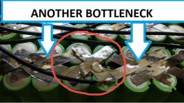
3. So you have created ENORMOUS bottleneck at every series connection leading to nearly creating short because of melted heatshrink of cells.
4. You haven't even used barley paper gaskets on positive ends.
5. When trying to repair it aka 'save it' you still did not have a clue how current passes. I am talking about this picture:bottleneckk.jpg
You still have current passing by only 2 thin nickel strips...

What you should have done.
1. Design pack so there are more series connections. Ideally as much as cells in parallel.
2. Use more layers of nickel strip. There were test on forum(which you of course did not read) which determined that for 0.15*7mm nickel you should not exceed 5A(cont.) so for every cell you should have 2 layers of nickel strip.
3. Use protection at positive ends. Barley paper gaskets are very cheap.

See? It's not hard.

And in my opinion you still have very high Internal resistance. I get more than half less (50-70mOhm) at 9P of GA cells when Adaptto measures it. But my pack is of course done with generous amount of nickel so i don't waste precious Watts on heating up nickel.
Please don't think of this reply as a personal attack, it is not :)
Cheers and keep on upgrading :D
 
Obviously did some things wrong when building this, but I have to believe now that the resistance is about as good as it will get with the 12 g solid copper being soldered to all the cells. Contrary to "having no clue", I now KNOW how to build a pack after only my first try, and guess what?...Im ok with that lol...
My lowest resistance value according to the CA was .184 ohms. The best resistance value for my headway cells was .190 ohms, and they used thick steel in connecting each cell.
I have another pack that I built unfortunately the same as the first. According to the reader who knows exactly how to build battery packs, this design is completely flawed.A friend of mine was using the pack on a stock ebike and after experiencing what happened to mine I got it back and got into it. Now blue or heated connections like mine but he didnt have a watt meter of any kind to determine voltage sag or anything else. I am going to repair this pack, but I am going to modify each SERIES connection with the same copper solid core wire and then test. Your saying that the parallel connections are bottle necked but after doing this, I will install in my bike, limit the current to 29 amps and test. If the resistance is the same as my 92 volt pack then I have to assume that the parallel connections are not the problem but the series connections, which I dont think is going to happen,but I have to test and see for myself.If the resistance, voltage sag is worse than my pack then I know the parallel strips have to go and I will redo the pack as I redid mine.

The one thing I did notice but had "no clue" about was how thin the plastic is surrounding the positive terminal and protecting the cell from shorting from the positive to the negative case. Seems that the cells need this added protection which I will do with the next pack.

Will report back when I re-test.

P.S. I do not believe that there is still high resistance using solid copper wire verses ANY VERSION of nickle strip, as I demonstrated that now the resistance is less than my headway cells.

I do appreciate all the feedback.

John
 
Headway cells are NOT a good standard to judge anything by ! :wink:
Ideally,..if you want something to judge by,... you should measure the DCiR of the cells you are using, then calculate the theoretical resistance of the pack you have built assuming zero resistance on the interconnects.
..Then see how close to that theoretical minimum you have managed to get .
 
Hillhater said:
Headway cells are NOT a good standard to judge anything by ! :wink:
Ideally,..if you want something to judge by,... you should measure the DCiR of the cells you are using, then calculate the theoretical resistance of the pack you have built assuming zero resistance on the interconnects.
..Then see how close to that theoretical minimum you have managed to get .


The only thing im interested in is the resistance of the pack, and currently the only thing I have to compare are my headway cells. I currently do not have anything to achieve this measurement.

I found an article that measured the resistance of a Panasonic NCR18650B cell at 55 mohms and a Headway cell at 17 mohms. So, if this is to be believed, without calculating the total resistance of the pack (Both the headways and the Panasonic cells) which I dont know how to do, then something is amiss...currently the Panasonic pack has a resistance of 185ohms and the best the headways had was 190+ ohms. Perhaps the resistance of the headways is because they have about 500 cycles on them?...dont know if this would cause the resistance to increase?

Given the figures above, and assuming they are correct, does anyone know how to calculate the total resistance of the pack assuming no resistance between connections (which is impossible)?...Im assuming that whatever figure is calculated would be higher than the cells themselves which would then account for the amount of resistance of the soldered copper.

John
 
eTrike said:
The math is easy to put into a spreadsheet for future use but you can use online calcs as well: http://www.1728.org/resistrs.htm

For a 55mOhm cell in 8P fill in 8 of the available 10 slots in that link with .055. The result is: 0.006875
or ~7mOhm.

0.006875 * 24 cells in series= 0.165 or 165mOhm.

Headway cells are said to be decently powerful. NCRB are not. /shrug

Ok..lol...what is the relationship to my pack resistance of 186 ohms?

Your statement does not pan out. The controller is set for 65 amps. When I first finished this battery it would only pull 37 amps. It now pulls 55 amps. The headways pulled 55 amps. The both pull the same and both produce about 4400 watts.

John
 
eTrike said:
~165/185= 89% of your sag is IR, so you're doing well. Both setups peg your controller but I was speaking in defense of headways as comparing Wh:Wh they are more powerful. NCRB struggle with 5A/cell. How many Ah were headways?

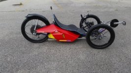
I had 24 headways (15ah). Its funny...on my trike, with the same cells the controller would pull 65 amps...so im not sure whats going on, although the trike weighed less and the motor on the trike is a Clyte H4080..trikeend.jpg

Well that is good..89% is a good result..not sure where the heck any other resistance is other than the cells...

Stats:
10 amps they sag 2 volts
15 amps they sag 3 volts and 25 amps 5 volts..

Thanks for the info!
 
Back
Top