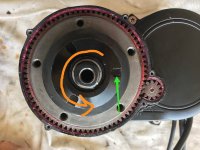
Here are some scope measurements of the V2 motor ‘hall’ sensor output at the 4-pin connector in the controller. There are 4 wires: red (assumed VCC), black (assumed GND), green and blue. I apologise if this reads as if I don’t know how to use a scope or know ‘lectroniks. That’s because I don’t. Bear with me.
This is the voltage between V+ (red) and GND (black) with display ON.
Now we change to scope mode. You may read the gain/settings at the top of each screen. The Fluke has an auto settings function for idiots like me which makes seeing consistent screens in images a nuisance but this is best I could do. Hereafter channel A is connected to the green sensor wire, channel B is connected to the blue sensor wire.
a) This is at rest. It’s the same whether the display is booted or not.

b) This is with the display powered up & crank driven by a drill (hex bolt head in chuck driving the hex of a crank fixing setscrew). The drill causes a strange distortion of both channels either because it’s a cheap Chinese drill that leaks current or because the drill speed control is rubbish and vibrates.

c) Now with a third channel enabled. The grey shape is A vs. B (or X-Y for scope people). This is at rest, powered up.

d) This is drill-driven, just at the point where the motor kicks in (more about that later).
View attachment 4
e) This is manually cranked, with one crank arm attached, just as the motor kicks in. This is hard to do & needs 3 hands so you are seeing the screen holding an image in the seconds it takes to pick up a phone.

f) Once more, as (e).

(g) And again.

I’m puzzled as to why channel A appears to be the only signal channel. I was expecting to see a signal in 2 channels. Equally puzzled as to why channel A voltage drops as the motor kicks in, is this sensor phase shift?
It is instructive to comment on what is physically happening here. The motor is sitting on a bench under it’s own weight and driven from the chainring side either by drill or by hand crank against no load. This is a rather unstable environment and I assumed would be pretty difficult to apply enough dragging torque to obtain a signal. Not so.
Cranking the motor gently up to a cadence of about 60 achieves nothing, 80, the same - the motor doesn’t initiate assist. Simply applying a drag to the chainwheel outer cover with hand pressure whilst the crank is rotating is enough to get the motor to kick in. To be clear,
without that torque, the motor won’t run. Similarly, applying hand torque
without rotation does not start it. Having fired it up it will run happily for as long as the crank is rotating. Sometimes the required torque is high, needing a firm grip (and a fast reaction to withdraw fingers) sometimes it is almost nothing. Sometimes it then runs fast, sometimes slow. It is inconsistent and unpredictable in the extreme. I tried this at least 40 times.
I wondered if I could get the motor to start at all with torque alone. Certainly not with hand pressure but stupidly jamming a screwdriver against the casing did. It also bent & threw the screwdriver 10m. Now there is a rough spot once per crank revolution. This motor is a torque monster.
Measurements aside, it appears there is an element of torque sensing but it is set with a very low threshold if the crank is turning or it acts as a foot switch and doesn’t have modulation i.e. crude. Without manipulating the motor gently on the bench this way the torque-sense/switch would be undetectable because loads on a real bike are way higher. 2 ways to look at this, either we have an incredibly sensitive torque-sensor that is a reprogram dream, or, it’s a switch.
Either way, color me surprised. What can you tell from the scope?


.jpg")


