Not simple BLDC controller It RUNS! :)

goodmorning from holland

sorry for my englisch
thank you for the update
I will wait whit patient
I said this because ,i have follow a lot of controller topics and every time they end without results
 
J-aprilia-N said:
goodmorning from holland

sorry for my englisch
thank you for the update
I will wait whit patient
I said this because ,i have follow a lot of controller topics and every time they end without results
Yes if there is one thing I hate its the waiting! I'm working on it. I am going to finish the PICkit lessons today! This is all new to me. But I love it I want to be the creator there is nothing more exciting then knowing when I'm done if I want to add a feature I just have to write the code and program it!
 
found some interesting stuff:

http://www.microchip.com/wwwcategory/TaxonomySearch.aspx?show=Application%20Notes&ShowField=no

if you select 'permanent magnet synchronous motors' under "select an application', 'motor control' you will find

http://www.microchip.com/stellent/idcplg?IdcService=SS_GET_PAGE&nodeId=1824&appnote=en025522

with the title "AN1017 - Sinusoidal Control of PMSM Motors with dsPIC30F / dsPIC33F/ dsPIC33E DSC"
complete with C-code and everything...
 
Remember, sinewave commutation is only better for motors that have a sinus BEMF. A ton of motors out there, including Astro's and most hubs have a more trap than sine pattern, and will run more poorly on sine.

Running sine also gives you a disadvantage in power at speed once the RPM of the motor has reached a point where it no longer in current limiting. Or, you could look at it as, the sinwave driven motor needs a higher voltage pack and higher voltage FETs to have equal performance to a trap motor at high speeds.

Your ON conduction period is also reduced, even when exiting current limiting, so you would think you would need to oversize the FET array for a given amount of phase current, however, by letting current fall off smoothly, it doesn't have to absorb as much energy in freewheeling currents, so thermally it's generally a wash, or even favoring sinus in some applications.

Things it does that are helpful, more quiet low RPM operation. A tiny bit more efficiency in motors with sinus BEMF, a tiny bit worse in motors with trap BEMF.


In a controller, having sinus control function is kinda very very low on the list of things that matter IMHO. And if you're racing, you simply wouldn't want it.

Implementing-Embedded-Speed-Control-for-Brushless-DC-Motors-Part-4
 
I agree. Sinusoidal signals are not the holy grail.
I've put this on the back burner as I haven't even finished my current
bike yet but I will occasionally work towards this.

Most motors are not sinusoidal therefore I'm thinking about a system which
is 'self learning'. If you spin a motor and switch off all the power transistors
an intelligent controller can measure it's back EMF and use this waveform instead of a sine wave.
Second, and much more important I think, the controller can find the phase-relation
between the hall sensors and the back EMF. I think many people don't have
their hall sensors in the correct spot (I mean you're easely off by
15 to 30 degrees) so a self-calibration would be nice.

What I'm further thinking of... based on the hall sensors it should have a phase-
estimator. When the controller has the capability to measure the motor currents
you can lock those to the estimated phase and have an automatic timing
advance to overcome the effects of motor inductance.

Lastly the controller can use the estimated phase to output a version of the earlier
measured back-emf waveform such that the motor current is equal to what the
user wants (so: current /torque based throttle)
 
Lebowski- That would be killer. WAY better than sinus could ever be, as no motors is ever perfectly sinus.
 
I was already hoping to have a learn function with this controller where it learns the halls! You can simply hook the halls up any way you want and spin the motor whith your hand or something at a steady speed and the controller will learn the hall positions! No more trying and watching the twitches and switching wires. Because I belive the twitches are responsible for at least 30 blown mosfets from collossus!!
 
I'm building a model of the motor and controller in LTSpice, like what I did for
my power controller (I posted a lot of LTSpice schematics in my power controller
thread). I think building a functioning controller in LTSpice is a good first step.
With the power controller it turned out LTSpice can simulate a discrete time
signal processing system in combination with real transistors / inductors
etc.

for a free copy of LTSpice (runs also very well under UBUNTU with Wine):

http://www.linear.com/designtools/software/#LTspice
 
I found a big but fast current sensor 90% in 1uS ! http://aac.proxy.voicestar.com/product_images/19_spec_sheet.pdf

Cant find a price but I think it might not be to hard to build!!!
 
I have some ideas for current and voltage filtering circuits, but picking their pole locations depends quite strongly on what the design minimum PWM frequency and design maximum motor electrical speed will be. Arlo, if you can provide those two numbers, I can provide a hybrid analog+digital current and voltage filter design that will perform much better than what you typically find in the uC vendor's app notes.
 
Have not got to the pwm part yeat. As for the electrical rpm this dis pic chip is fast and thats why bigmoos recomended it. The current motor im working on is 10 poll pairs so 10x the regular rpm so i would say as a buffer lets aim for at least 100,000 erpm maybe more i would hate to be limited but.... I do plan to spin to at least 80,000 e-rpm!
 
OK, so here goes. This technique is sortof a poor-man's Sigma-Delta converter, but with a moving window average filter instead of a sinc filter (for good reason!).

For the sake of discussion, lets assume a nominal PWM frequency of 18 kHz. Its a pinch faster than some of the existing available drives, slow enough to control with a reasonable gate drive, and near the limit of human hearing, typically on the inaudible side of that limit. So it should be in the ballpark.

The hard part is that a 1.4 khz line freq (~80k erpm) is barely one decade less than the pwm frequency. And there is a ton of noise at the pwm freq and its harmonics. Mostly odd harmonics, but there will be some even harmonics, too at any time the duty cycle isn't exactly 50%. My idea is to use four mechanisms working together to eliminate the noise, while still allowing for a very fast fault current detection.

First, if the pwm carrier is an up/down-counting triangular wave (as opposed to a sawtooth), with synchronous rectification, then the motor's ripple voltage and current are actually at 2x the pwm silicon frequency. Assuming a trapezoidal drive pattern for the moment (SVPWM is similar), the switching sequence goes:
(leg, leg, motor volts), where leg == 1 for high switch on, and 0 for low side on, B is battery voltage
(1, 1, 0) -> (0, 1, B+) -> (0, 0, 0) -> (0, 1, B+) -> (1, 1, 0).

While each phase leg follows the sequence 1->0->1, with only one falling and one rising edge, the motor saw a pair of B+ and a pair of 0 voltages. So, you have effectively doubled the motor's voltage frequency, halved its ripple current, and stretched the gap between f_line and f_pwm by a factor of 2.

Second, oversample the motor current and perform a simple average over the results. The advantage here is an exact harmonic cancellation of the ripple current and its first few harmonics. For an N-th order moving window average, the first harmonic to be canceled is f_oversample/N. The first non-cancelled frequency will be at f_oversample, which will appear as DC. Above a certain threshold, non-harmonic switching noise will be a major factor. So, why do you care about all this noise? Everything above the nyquist frequency of your control loop will alias in if you don't filter it out. PWM ripple current will be the dominant source of noise up to a point, and then switching noise will be a factor.

Third, place a two-pole analog Bessel filter in front of your ADC. Why a Bessel filter, and not a Butterworth filter? Because the butterworth filter is not minimum-phase or linear phase, and phase delay at the line frequency will be a serious problem for closed-loop control. Why 2 poles? Because its easy to get 2 poles with just one opamp, and I don't think you need many more than that. You can estimate what the noise level of that N-th order harmonic will be, and stamp it down to less than the detectability of your ADC. I'll just leave the mathematics behind that decision to the GNU Octave script that I attached.

Given the following nominal parameters:
f_line = 1.4 kHz
f_pwm = 18 kHz
N_oversample = 6
N_poles = 2;
L = 10 uH inductance (just about the worst we can imagine right now)
V = 72 VDC
10-bits of (pwm-) noise-free current measurement
400A full scale current sensor

The attached script places a two-pole Bessel filter at 33 kHz, with only 11 degrees of phase delay at f_line, and > 10 kHz of usable bandwidth. This is the Bode plot of the total filter's transfer function.
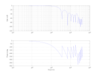
current-filter.png
The slightly higher hump at ~200 kHz is the first uncanceled harmonic, which aliases in as DC. The low-pointing spikes in the gain plot are the canceled harmonics. Everything higher than the first negative spike will alias in, but -48 dB is the threshold of detection for a 10-bit ADC. Don't read anything into the depth of those spikes, they are effectively infinite for a digital filter.

Fourth, route the un-filtered original signal to a pair of analog comparators for fault detection, because that's about the only way you can get fast enough to save the 'fets. I'll try to get a schematic of the analog filtering circuits up later, but it may be a few days before I can get a free round tuit.
 

Attachments

  • current-filtering.m.gz
    1.5 KB · Views: 84
The motor Im dealing with has 8uH inductance! But I may wind it different and go way up on the volts.
 
That's why I included the script. Just change the params and it'll compute the result according to that particular methodology.
 
Great thread folks. I haven't had time to work on my controller, but it is nice to read about others progress and learn a few things.

Just for future reference of those wanting to try AVR chips for this application, the Atmel ATMega32M1 looks interesting. It has the 'stuff to control BLDC motors. I know you folks are using the PIC, but I have a few of these AVRs and plan to try them at some point unless there is a reason not to. I would appreciate any comments you might have on these. I have a set of PCBs mostly designed for them in another thread on here somewhere.

ATMega32M1 has:
32 pins
20 MIPS processing rate at 20 MHZ clock
it contains a power stage controller which has:
6 complementary outputs to control 3 half bridges
programmable dead time
12 bit pwm
64 mhz pwm
programmable ADC trigger
automatic overlap protection
3 failsafe emergency inputs - force outputs to safe state - programmable by fuse selections in hardware programming
built in DAC and comparators to make adjustable setpoints for emergency shutdown

four fast analog comparators for things like sensorless detection and overcurrent detection
differential amplifier for current measurement

Free world class GNU C compiler
Free programming environment for asm language and simulation

Many programmers available from $15-50

Has bootloader capability so software can be loaded via serial once a bootloader is installed (don't need a programmer then)

It costs about $5 in small quantities

It also has a few more things for future growth like CANbus / LIN / UART interfaces, etc.

More info on this chip here:

http://www.atmel.com/dyn/products/product_docs.asp?category_id=163&family_id=607&subfamily_id=1723&part_id=4307

Thanks in advance for any comments on this part for this application.
 
Thanks for the post Alan.
When I started this thread I knew nothing about Pic programing and now I know a little more and would have liked to know more about the other chips as well. But I will never learn if I don't get my feet wet (or dive in lol) Its all good though I have a free compiler and as I understand more about all this I may try other chips as well. This whole thread is to be open source so anyone in the world can try what we are working on here. I have done most the pickit lessons and I feel I need to do them over and over so it sinks in better. But I am very excited about this and always will be. The idea from starting from true scratch has been in my blood for a long long time. It used to be with the ICE industry so I built a megasquirt 2 efi system because it was as close as I could get. Now I am in way deeper!!! And I must admit non of this would be possible with out the help from all the others on this forum!
 
I've been reading through the documentation of the 30F4011-30 in preparation for this build (only 1200 pages :shock: )
(don't worry, it's like an encyclopedia, you're not supposed to read it front to back)

This processor fits the requirements I forsee for my algorithm:
- 3 capture channels to capture to content of a timer based on edges from hall sensors
- 2 ADC channels for current measurement
- 3 additional ADC channels for motor waveform measurement (for calibration and possible sensorless
running after a sensored startup phase)
- 6 motor PWM outputs with programmable dead time
- RS232 interface. I plan to use the simple terminal programma that comes with either Linux or Windows.
The processor can then send simple menues to the PC where you can change all kinds of options
and parameters, and also receive back-EMF waveforms and information about hall sensor placement.
- possible I2C interface for peripheral control (I'm contemplating using 3 I2C digital variable resistors
to change the gain when measuring back-EMF motor voltages during calibration stage.
- DSP. A digital signal processor on board will certainly help especially for waveform sampling and processing
during calibration.
- EEPROM at least 256 bytes, preferably 512 bytes for back-EMF waveform storage.
- Even more EEPROM (around two times 64 x 16, so 256 bytes) for x-y to angle-amplitude transformation tables
- simple DIL with 0.1" pin spacing for easy soldering and breadboarding (I don't have a fancy SMD soldering
iron and am too cheap to design a custom PCB)
- but the main reason: I got a few 30F4011-30's for free ( :oops: )

I don't know how the Atmel fits this... do you guys have stock in Atmel ? So many people recommended them
but I just don't like their datasheets, it's unreadable. I'm especially dependent on a good datasheet as I plan
to program the whole shebang in Assembler (to my humble opinion assembler is for men with hair on their chest,
C is for little girls).
Especially with the RS232 interface I think during the development the intermediate results could already be
very interesting. I would start by programming the calibration part, when finished this could already be used to
(over RS232) display errors in the hall sensor placement.

At the moment I'm up to my neck in epoxy glue as I'm making a new coil-plate for my motor. The current one
in de motor doesn't have hall sensors. Also I want to add current measurement resistors at the star-connection
point of my WYE configurated coils as this is the easiest and cheapest way to measure phase currents.

After that I think maybe it's best to start a new thread which concentrates on the algorithm (not the hardware)...
 
We each have significantly different experience and slightly different goals, so our choices are going to be different. Nothing wrong with that.

I've spent a good chunk of my life programming low level hardware with C and Assembler and reading data sheets, and I have an inexpensive SMT hot air rework station and stereo microscope and prefer doing clean PCB layout to fiddling with haywired prototypes. I've done PIC and AVR hardware design and programming and prefer AVR. I've written compilers to generate assembly language from high level languages, and have written plenty of assembly language. I prefer Python and C these days, and the occasional assembly where it is really needed. But those are my choices and you must make your own.

Regardless of our different choices there is still a lot we can learn together and share in these threads. Thanks to all the contributors on ES, especially to those folks who really know this application space and take the time to help spread the knowledge.

Good luck on your controller.
 
So I just ordered some 5v regulators and some resistors from Tayda electronics and the A/D converter from microchip (they wont send samples to Canada :roll: )
But I should have all I need to build this now on its way or in stock! A couple weeks and I will be trying out a new prototype!
 
texaspyro said:
Do you have a Magic Smoke re-injector... you are going to need it :twisted:
No But I like fire and explosions and fireworks and welding flash! :mrgreen:
 
So I got a couple MCP4728 A/D Converters in the mail and man they are small.... Is there anything easier to work with or do I need to learn to soldier with a uber sharp tip? :lol:
 
Back
Top