One-Phase Generator Rewind to 3-Phase BLDC

JackB

10 W
Joined
Apr 28, 2013
Messages
86
Location
Sacramento, CA
I am rewinding/modifying a generator head from 120vac single phase into a 3-phase BLDC.
I think I know how to do this, but before I spend the many hours it takes to rewind, I'd like to make sure
I'm doing it right. ;)

This generator head stator has 30 slots. Picture below after I have removed the old windings:
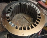
hfgenstatorempty.jpg

Given 3-phases, the poles must be divisible by 3, so I can only do 3, 5, or 10 poles.
It was planning to do 10 poles, which means winding a coil around each slot, similiar to how outrunners/hub motors are wound.
I could use some assurance on winding rotation direction and the magnet poles.
There are 2 magnets for each pole, and when alternated N-S,
there is an even number of 20 magnets, which means the N magnets all align with each pole (and S as well when rotated).
So if I understand correctly, this means all the coils should be wound the same direction, essentially ABCABCABC, etc, right?
 
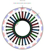
Thanks for that link. What it came up with for 20 magnets is this, which is what I was thinking of doing,
but not with the empty ones. This is also ABCABC. Why skip the even ones?

hfgen20pole.jpg
 
So I did the layout without the skipped windings, and it seems to make sense to me,
I redid as a liner layout, and here are the first three commutations, the next three are just the reversed polarity.
Is there something I missing? :?:


10 poles, 10 magnets look better to me. And what was that, a 2 pole alternator? Pretty thick back iron to carry around if you're planning to make a bike motor from this.
 
major said:
10 poles, 10 magnets look better to me. And what was that, a 2 pole alternator? Pretty thick back iron to carry around if you're planning to make a bike motor from this.

Yes, why does it have such thick back iron? I'm far from a motor expert, but it seems this is needed when the coils are overlapping windings,
which is what that 10-pole-10-magnet winding would be. I'm still confused on how to wind those..any pointers on that i'd appreciate, google was not my friend..

The plan was to lighten it by drilling big holes in the back iron. It needs to fit back in the generator housing it came from.
This is a harbor freight 800 watt generator, I'm modifying to be self-starting and more efficient and lighter weight.
You can see this project on http://www.electric-boat-forum.com
 
Cross sectional area of back iron needs to support half of the flux per pole. Fewer poles mean higher flux per pole. Obviously 2 pole being as low as you go, so back iron is thick. But Synchronous speed of 3600 for 60 Hz alternator sets pole count at 2 (1 pair). That was for the direct connect to generator yielding useable AC power. Going to a inverter controlled PM motor/generator allows pretty much any RPM/frequency since it is converted to DC anyway. Good luck with the project.
 
So I think I understand why the program output layout skipped the even fingers.
It is quite difficult to get good fill winding two fingers that share a slot.
It is much easier to wind a single finger and fill the slot.

As I prepared to drill lighten holes in the stator, it occurred to me perhaps what I should
do is drill hole to elongate the slots so I can wind more copper in them.
My concern is when drilling holes, the laminations get shorted from the rough drilled edges.
It wouldn't have any effect on lighten holes, but how badly would this effect the slot elongation?
 
So I have removed the unneeded stator teeth, and did some major lightening and grinding on this stator.
It can now accept a significant larger amount of windings on the teeth, and will be much easier to wind as well.
 
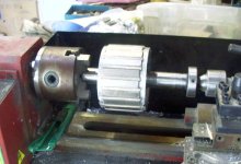
I've finished building the new rotor. Used some aluminum disks made on the lathe, and epoxied the magnets.
I'm wondering how to balance this rotor. The lathe will spin up to 2500rpm, and it doesn't vibrate that I can tell,
but it is pretty secure in the lathe.

hfrotormag.jpg
 
I think you have ruined the stator now :|
They should be isolated from each other and it looks like the drill work you did to remove the unneeded teeth are now actually shorting all the lams together and now it is like having one big solid stator.
I might be wrong though.

Otherwise great work :)
 
The lams were already electrically connected to each other, they are welded together at the edges.
The drilling/grinding does increase the area connected, I'm convinced it doesn't matter much at all, but I am just a motor 'jack'. :)
 
Back
Top