Tombombadil1988
1 mW
After cutting the PCB like in the picture of Nordel, will the buttons still work or just the potentiometer?
The Buttons are connected with 3 wires (colored like the letters in the pic [original nintendo nunchuck]) to the potentiometer, I assume they still work, but I don't know.Tombombadil1988 said:After cutting the PCB like in the picture of Nordel, will the buttons still work or just the potentiometer?
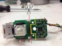
Pcb seen from below: left + | middle pwm | right gndNordel said:But i don't know wich one is 5v, gnd or pwm, cause I don't have multimeter atm:/ if someone knows that would be nice
Arduino: 1.6.5 (Windows 7), Platine: "Arduino Nano, ATmega328"

Build-Optionen wurden verändert, alles wird neu gebaut

Verwende die Bibliothek SPI im Ordner: C:\Program Files (x86)\Arduino\hardware\arduino\avr\libraries\SPI

Verwende die Bibliothek RF24-master im Ordner: C:\Users\Rech\Documents\Arduino\libraries\RF24-master (legacy)


C:\Program Files (x86)\Arduino\hardware\tools\avr/bin/avr-g++ -c -g -Os -w -fno-exceptions -ffunction-sections -fdata-sections -fno-threadsafe-statics -MMD -mmcu=atmega328p -DF_CPU=16000000L -DARDUINO=10605 -DARDUINO_AVR_NANO -DARDUINO_ARCH_AVR -IC:\Program Files (x86)\Arduino\hardware\arduino\avr\cores\arduino -IC:\Program Files (x86)\Arduino\hardware\arduino\avr\variants\eightanaloginputs -IC:\Program Files (x86)\Arduino\hardware\arduino\avr\libraries\SPI -IC:\Users\Rech\Documents\Arduino\libraries\RF24-master C:\Users\Rech\AppData\Local\Temp\build977424018304353579.tmp\nrf24l01_transmitter.cpp -o C:\Users\Rech\AppData\Local\Temp\build977424018304353579.tmp\nrf24l01_transmitter.cpp.o

nrf24l01_transmitter.ino: In function 'void loop()':
nrf24l01_transmitter.ino:111:71: error: no matching function for call to 'RF24::write(unsigned char [4], int&, bool)'
nrf24l01_transmitter.ino:111:71: note: candidate is:
In file included from nrf24l01_transmitter.ino:2:0:
C:\Users\Rech\Documents\Arduino\libraries\RF24-master/RF24.h:281:8: note: bool RF24::write(const void*, uint8_t)
   bool write( const void* buf, uint8_t len );
        ^
C:\Users\Rech\Documents\Arduino\libraries\RF24-master/RF24.h:281:8: note:   candidate expects 2 arguments, 3 provided
no matching function for call to 'RF24::write(unsigned char [4], int&, bool)'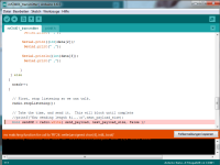
Nordel said:I've successfully uploaded the code on my receiver arduino.
But when I try uploading transmitter code I get this error:
Code:Arduino: 1.6.5 (Windows 7), Platine: "Arduino Nano, ATmega328" Build-Optionen wurden verändert, alles wird neu gebaut Verwende die Bibliothek SPI im Ordner: C:\Program Files (x86)\Arduino\hardware\arduino\avr\libraries\SPI Verwende die Bibliothek RF24-master im Ordner: C:\Users\Rech\Documents\Arduino\libraries\RF24-master (legacy) C:\Program Files (x86)\Arduino\hardware\tools\avr/bin/avr-g++ -c -g -Os -w -fno-exceptions -ffunction-sections -fdata-sections -fno-threadsafe-statics -MMD -mmcu=atmega328p -DF_CPU=16000000L -DARDUINO=10605 -DARDUINO_AVR_NANO -DARDUINO_ARCH_AVR -IC:\Program Files (x86)\Arduino\hardware\arduino\avr\cores\arduino -IC:\Program Files (x86)\Arduino\hardware\arduino\avr\variants\eightanaloginputs -IC:\Program Files (x86)\Arduino\hardware\arduino\avr\libraries\SPI -IC:\Users\Rech\Documents\Arduino\libraries\RF24-master C:\Users\Rech\AppData\Local\Temp\build977424018304353579.tmp\nrf24l01_transmitter.cpp -o C:\Users\Rech\AppData\Local\Temp\build977424018304353579.tmp\nrf24l01_transmitter.cpp.o nrf24l01_transmitter.ino: In function 'void loop()': nrf24l01_transmitter.ino:111:71: error: no matching function for call to 'RF24::write(unsigned char [4], int&, bool)' nrf24l01_transmitter.ino:111:71: note: candidate is: In file included from nrf24l01_transmitter.ino:2:0: C:\Users\Rech\Documents\Arduino\libraries\RF24-master/RF24.h:281:8: note: bool RF24::write(const void*, uint8_t) bool write( const void* buf, uint8_t len ); ^ C:\Users\Rech\Documents\Arduino\libraries\RF24-master/RF24.h:281:8: note: candidate expects 2 arguments, 3 provided no matching function for call to 'RF24::write(unsigned char [4], int&, bool)'
Please guys, I need your help! Don't want to go with a bulky RC remote-.-
Nordle said:Thank you!
I soldered everything together and it seems to work fine. Only not sure if I have to power the potentiometer directly from the Lipo or from the Arduino 3,3v/gnd or doesn't matter?
This should also work with other potentiometers? Cause I have some laying around and in mind to design my own controller
I'm just bad in electronic stuff
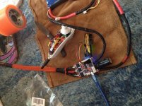
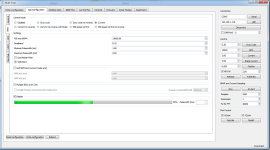

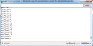
I did, this and it seems that this part is fine.erwincoumans said:You should first check if the transmitter reads ok values from the potentiometer, using Serial connection.
In the Arduino IDE,
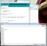
uncomment line 70+71 Serial.println(potValueA) and upload/run the modified script nrf24l01_transmitter and open
Tools/Serial Monitor using 115200 Baud rate and check output.
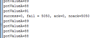
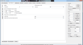
Did you enable 'safe start' in the VESC Applications/PPM options? If not, please do so and reboot VESC.Nordle said:but if so I can't explain the video, the random motor twists begin when i power my tx.
I did enable safe start.erwincoumans said:Did you enable 'safe start' in the VESC Applications/PPM options? If not, please do so and reboot VESC.Nordle said:but if so I can't explain the video, the random motor twists begin when i power my tx.
Indeed, your two Arduino's don't communicate. Did you connect the nrf42L01+ in both Arduinos? Did you try some example sketches like ping-pong?
First make sure the 'pingpair' sketch works, use pin 7 to choose receiver or transmitter (or hard-code it in the script).
If that doesn't work, check your wiring of Arduino and nrf24L01+ and use the Arduino forums for help.
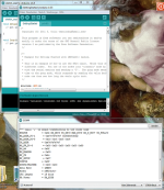
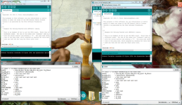
Maniacbug's guide says:
Instead, if you see a lot of zeroes everywhere, something is wrong with your connections. Double check them all again! In the course of making this tutorial, I even switched two of the wires myself and had to re-solder them. If you hooked everything else up right, you will see numbers just like those above.Ok, gonno try again tommorow while powering rx from power supply. And also my connection does not drop, I don't even get a connection:/Pedrodemio said:I had a similar problem if i powered the receiver arduino from USB, lots of connection drop
