PaulD's Old Race Bike

acuteaero

100 W
Joined
May 8, 2011
Messages
172
Location
SF Bay Area, CA
In December 2011 PaulD posted a new thread about his plans to give away his old race bike (winner at the death race and the Socal Grange race) to an E-S member of his choice. I wrote him a letter and he decided to give it to me. I picked it up from him in Ashland in January 2012. That thread is here: http://endless-sphere.com/forums/viewtopic.php?f=3&t=34716

I promised to maintain the bike, take it racing and document the work on it here on E-S.

Without further ado: PaulD's Race Bike

IMG_0113.JPG


Initial Specifications: (January 2012)

Motor: Turnigy C80100 130 kV (stock wind) Internal and External hall sensors installed.
Controller: Grin Tech 12 fet.
Battery pack: TBD (not included with bike)
1st stage reduction: 26t/50t Gates GT2 belt 5mm pitch 15mm wide. 80t belt. Parts from SDP/SI
2nd stage reduction: ~1:5 219 chain. Extron rear sprocket rigidly mounted to disk brake hub
Motor Freewheel: Flanged ENO mounted inside 50t belt pulley, on jackshaft.
Fork: Rock Shox Revelation
Front Brake: Avid Juicy 7, 183mm rotor
Rear brake: Shimano rim
Pedal drivetrain: Shimano 9spd
Frame: PaulD Custom chromoly brazed/TIG welded
Tires: Maxxis Hookwork 24x2.5

Weight:

Frame (with fork, seat, cranks) 21.5 lbs
Bike (with wheels, motor- no battery, controller) 40.5 lbs

(I'll update this post with additional specs, better pics, current specs as I go!)
 
Rebuilding the Turnigy HXT 80-100 130KV motor (C80100 KV130)

PaulD told me when I picked up the bike that there was some mechanical maintenence to be done, he had observed wear on the jackshaft under the bearings. As well some screws were missing in the motor can and others were worn and cammed-out. I was not sure how much of a rebuild the motor would require- it soon became evident that it needed some work.

The first sign of trouble was the large amount of axial play of the rotor with respect to the stator. After taking the motor apart it became clear that the retaining ring that holds the shaft between the rear and front bearings was deformed and useless. I also saw a fair amount of wear on the shaft under the front outboard bearing in the motor mount plate.

BeforeDWGAnnotated.png


I asked PaulD about the design of this arrangement- as it seems that the front outboard bearing overconstrains the shaft. He said he was not confident about the stock internal bearings ability to reliably take the side-loading from the belt drive, but was not confident enough in the outboard bearing's ridgidity and allignment to remove the internal bearing. The outboard bearing was held into the laser-cut mounting plate nearly entirely with Loctite!

I decided to make a new mounting plate with an accurately sized and placed bearing bore, press a bearing into it and remove the original front motor bearing.

AfterDWGAnnotated.png


Here are the motor and jackshaft parts just after disassembly

IMG_0056.JPG


Here are the new motor plates, just out of the CNC. I used the same method to make them as is documented here: http://endless-sphere.com/forums/viewtopic.php?f=30&t=36803#p547606

0306121918.jpg


Here's the new motor plate ready to be installed on the motor

IMG_0074.JPG


and installed

IMG_0075.JPG


I then turned my attention to the motor shaft. I needed to make a new one becuase of the wear on the old one and the moved retaining ring location. I purchased two different kinds of shaft stock- "drive shaft" and hardened shaft stock. The drive shaft was .001" under nominal size, the hardened shaft was .0001 undersize. I decided to use the drive shaft for ease of machining and becuase the hardened shaft would make it pretty difficult to service the motor the fit is so tight inside the bearings. I got all new replacement bearings.

Paul had milled flats on the shafts- I decided to dimple the shaft instead based on what I'd heard around E-S. I decided to take it one step further and use 90 degree cone-pointed set screws and drill dimples with a 90 degree drill. Here is the setup I used to drill two dimples exactly 180 degrees apart.

IMG_0080.JPG


The shaft is clamped into the 123 block and the precision square alligns the block square to the table of the machine. Then I can open the vise and reorient the shaft with the square against the block to rotate 180 degrees. (could work for 90 too!)

IMG_0081.JPG


Tool I used was a 3/8" dia. carbide 90 degree point "Drill Mill" made by Melin. I also used the same tool later on to dimple 60RC case-hardened shaft. With super gentile hand feed it worked great.

Dimpled shaft and new set-screws ready for installation.

IMG_0082.JPG


Last order of business before reassembly- the windings on some of the teeth were very loose- I daubed a little epoxy on them just to prevent disaster. I hope to switch to a re-wound motor sometime so I didn't spend too much time making it pretty.

IMG_0084.JPG


Epoxy curing oven

IMG_0083.JPG


Finally ready for assembly!

IMG_0087.JPG


About the front motor pulley- PaulD had bored out a stock SDP/SI 26t pulley to 12mm and used setscrews to fasten it- unfortunately the bore was pretty loose and bad and the pulley wobbled a lot. I decided to switch it to use a Trantorque bushing instead- they are very cool and easy to use! No set screws to gouge the shaft- easy to service. Thanks to Steve for the suggestion and for contributing the bushings to the project (they're expensive!)

Because the trantorque requires a much bigger ID bore I was able to save the old pulley by boring it out. I bored the pulley while chucking on the hub, then flipped it around and held a shaft in the chuck then used the trantorque to hold the pulley on the shaft. Worked great.

IMG_0085.JPG


IMG_0086.JPG


Done and done!

IMG_0089.JPG


IMG_0088.JPG


I'll describe my rebuild of the jackshaft next...
 
Rebuilding the Reduction Drive Jackshaft.

The Jackshaft on PaulD's old Race bike is a bit of a tricky one, as noted by PaulD himself- the bearings are closely spaced on the shaft and the angle between the line between the motor and jackshaft and the line between the axle and jackshaft is close enough to 180 that much of the tension forces due to the torque on both will constructively add to make a large twisting force on the jackshaft (with a respect to a vertical axis).

PaulD had used keyed shaft stock to make the jackshaft. After relatively little use it was developing pretty deep fretting. I figure the cause must be the high side forces on the shaft- combined with looseness caused by the shaft being about .001 undersize, plus running the keyway through the bearings.

I decided to replace the shaft and bearings with new bearings and a hardened shaft. The shaft is very simple. It's .625 diameter with a keyway and concentric drill in one end. The other end is turned down to accomodate the drive sprocket which is held on with a set screw.

I tried turning the hardened shaft but was having a lot of trouble holding a good diameter tolerance. The tools I was using were badly optimized for the job. When I realized that I had a .625 chucking reamer it became an easy decision to just bore the soft steel sprocket instead! The diameter difference was only about .040.

Indicate it in perfectly - I only have one of these!

IMG_0094.JPG


And ream it.

IMG_0095.JPG


I popped the old bearings out of the jackshaft tube and cleaned up the dried loctite. I installed the new bearings using a variety of tubular implements and a soft face mallet. Loctite Bearing Mount applied as well. Paul had described some trouble he had had finish boring the tube so I figured it was a good idea.

IMG_0099.JPG


New bearings on a spare shaft ready to install.

IMG_0096.JPG


Bearing tube ready to go, propped up on a pile of aluminum bits for support.

IMG_0097.JPG


Going, going,

IMG_0098.JPG


And gone

IMG_0101.JPG


The jackshaft itself:

IMG_0108.JPG


The sprocket slides over one end of the shaft and is fastened with a cone pt screw into a 90 deg dimple, as described above. Cutting the keyway was the real tricky part. I hadn't done any machining on case hard steel before- I was a bit nervous. First I tried a 7/64 5 flute carbide endmill, taking multiple depth cuts at low speed and tiny chipload. This proved to be a bust- even with depth cuts as small as .002 all the tips of the tool would break off in the first depth cut or two. I then switched to a 3/16 carbide 5 flute endmill with radiused corners and took one cut at full depth, full width. It worked without a hiccup. No discernable tool wear, even. I cut the slot just a little deep to compensate for the radiused corners. Moving the case hardened layer (.040 min thk, per the specs) up to the sides of the cutter instead of the tip seems to have helped a lot! Fortunately this keyway ended off the edge of the part so I side mill the whole thing- if not I would have pre-drilled one end with a carbide drill.

Slide it right in. Turned a bushing to capture the shaft from sliding back and forth.

IMG_0110.JPG


Done and done.

IMG_0111.JPG
 
Wow! Really really nice work man! Top notch! That is such a beautiful light bicycle too!
 
Miles said:
8)

PaulD made a good choice. :D

Can we have some more details on the epoxy curing oven? :mrgreen:


Yeah, seriously, that bike ended up in the right hands.
 
Incredible workmanship!
 
Thanks guys! I really appreciate the comments!!!

Here's the latest chapter of the story, brings us about up to current.

Maybe you're wondering- will it all work? I certainly was wondering that!

The next thing to do was to put it back together and test it. The only remaining major complaint about the bike's performance was the touchy throttle- it was difficult to smoothly lay into the power when accelerating. I had had ideas about possible solutions- potentially trying the CA current-controller throttle. To that effect I got out my spare CA- large screen stand alone version and wired up connectors for the throttle as per the CA manual.

IMG_0129.JPG


I spent a little time testing it and trying to tune it but was unable to find a good combo of gains to make the throttle response better. It tended really strongly to want to oscillate, and with the gains low enough to prevent that it became extremely sluggish. It may work with more tuning.

But- that may not be necesessary- I changed the half-twist Hall throttle for a Magura pot-based throttle with 10 turn trimpots on the high and low wires to tune the high and low output limits. This allowed me to set the limits of the throttle travel exactly at the points where the controller begins to deliver power and is maxed out. This resulted in a nice linear, sensitive easy to feather throttle. It feels fantastic and I think should work really well.

I mounted up the new CA and Cycle Analogger (slick!) as well as the aluminum battery holder that my rider (Miles K.) fabricated to hold the (temporary) 12s 10AH Zippy pack- As I was setting it up I noticed one quibble with the mechanical overhaul- after the long night making up the new jackshaft I had gotten hasty in drilling the hole in the belt-end of the shaft and had drilled it a couple thousandths out of concentric- a shoulder bolt goes in that hole that fits in a bearing that is pressed into the outboard end of the 50t belt sprocket (providing complimentary support for the bearing in the White freewheel) As a result the pulley wobbles just a tiny bit as the jackshaft spins. :evil: I will probably make up a new shaft (now that I've figured out a way to cut the keyway) and replace it- take it as an opportunity to take the drive apart again and see how it's wearing before the race.

So how does it work- in short great! Improved in every way! There is less drag in the motor - the motor freewheels to a stop much slower than it used to. Much less noise is made by the entire drive- it used to hit a certain speed and resonate- it would really wail. It's quieter overall and no longer resonates. The reduced drag (and a little dab of solder on the controller shunt :D ) make it feel significantly smoother and faster.

What's the ketch? (This story proves I am a bit of a noob!) When I put the motor together with the new thicker motor mount plate the screws to hold the external sensor ring were no longer long enough- so I switched to the internal sensors that PaulD had installed. They work great, but spin the motor the opposite direction than the external sensors. I pulled the jumper PaulD had put in the Fwd/Rev connector of the controller and all was good- little did I know auto-cruise was not disabled, and so switching from Rev->Fwd turned it on. I had a bit of a scary episode at the end of the street after making a little top speed run where the throttle seemed to be stuck at WOT. Wish I had video of that! As soon as I figured out what was going on I immediately disabled auto cruise!

IMG_0135.JPG


IMG_0136.JPG


IMG_0137.JPG


IMG_0138.JPG


So what's next to do? I have recieved notice that my Li cells have been shipped so I need to now prepare to build packs. I need to set up my charger. I need to have my rider practice on the bike and keep a careful watch for any signs of mechanical or electrical changes. I gave him the bike on Monday to ride during the week- he was so sad when the storm rolled in on Tuesday- this is not a rainy day bike!

[youtube]1q7rqiEGoUg[/youtube]

(my rider, Miles K)

IMG_0132.JPG


IMG_0131.JPG
 
Right on! Great job!
 
I am sure we can get the CA to work well for thrust-throttle.

Since you had such good luck by just increasing your throttle resolution (magura hack) I propose that we do the same for the CA Current throttle. First step (if you did not already do it) is to tighten up the voltage thresholds. That should increase resolution. Second would be to think hard about the current limit. The higher that limit is the lower the resolution the throttle will have. I had this problem back in the day with my 220A kelly controller. I had it set up for thrust control (and thrust cruise). Problem was that my 70 degrees of throttle rotation mapped to about 120battery amps of current so... I had no resolution. I corrected that by lowering my current limit. I gave up some off the line thrust but lowered motor temps significantly, increased efficiency and range, and made the bike much more ride-able.

Lately I tend to set the current limit closer to what I can actually pull from say... 10mph to 25mph. Again, a tad sluggish off the line but much easier on motors. No more 130A current limit for me :)

Anyhow.. the reason I am spraying verbal diarrhea in your AWESOME thread is because I am making a "wheelie bike" with thrust throttle and all of the battery weight over the rear axle. Next time you come over we can geek on your CA and try to tune in something useful.

You can ride my wheelie bike... 24S 20Ah battery mounted right over the rear axle... I think it will be a horrible machine.

-methods
 
methods said:
I am sure we can get the CA to work well for thrust-throttle.

When I come over next I'll bring the bike and we can play with the throttle- I have all the components connectorized- the throttles, pots, CA and controller- so it's easy to move parts in and out of the line. I really spent only a few minutes playing with the CA throttle- the manual is great and very complete but the learning curve is a little steep if you haven't got any experience with it. Not so sure about the wheelie bike though, mister. Sounds mostly like a lot of pain to me :lol:

Thanks again for the comments from everyone! I'm really glad you like the work I've done. I can't wait to get the final 18s battery pack put together and all setup. That should really bring the whole thing together. I can't wait for the race in April- I think it's going to be a HUGE party. :D

Fortunately the rain storm we have been having this week seems to be lessening as we go into the weekend and next week- so Miles K. can get some more riding in (lucky guy!)

Miles said:
Can we have some more details on the epoxy curing oven?
Psch. You should be able to tell that's highly sensitive information I have no business sharing! Maybe once I get my patent squared away I'll divulge whether I set it on Hi or Lo :mrgreen:
 
*Jump forward two months*

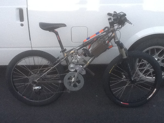
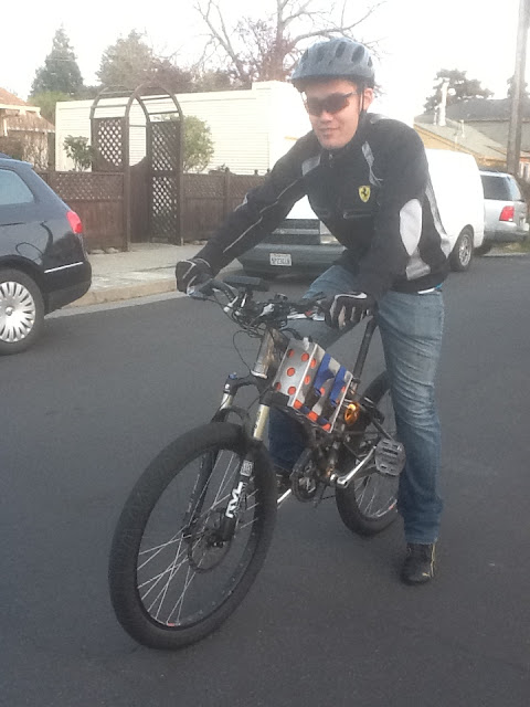
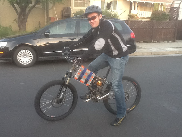
If you were paying close attention you might be aware of the results of the April race- I was there, the bike was there, running (when I took it out of the car, at least...) I had rider, batteries, chargers...

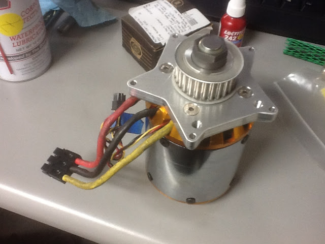
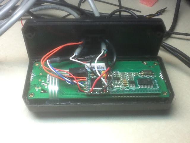
The bike arrived at the track with a 12fet controller I had bought from Lyen the previous day in San Francisco, and doubled the shunts on to stop the throttle cutting out (after being unable to track down C20- it appears to be unpopulated on this board, further investigation is required). Fudged the current settings a bit due to uncertainty from the shunt modification. During practice laps the rider blew up that controller- melted solder off the board and some FETs have gone bad. When Farfle arrived the next morning I borrowed his big 24 fet controller and wired it up- proceded to set the current limits way too high while hurrying to get set up for the race and the rider burned up the motor in about 1.5 laps. (of course after wheelieing the bike out from under him at the starting line.) A comedy of errors, starting down the trail of burned up parts that RC motor systems love to make...

After finishing the school semester a month and a half later I have focused my attention on figuring out what to do next- I have some months and a sufficient resources (time, money, and machine shop access) to do something cool and really make the bike better- first step is making up a plan.

I want
  • motor re-wound for better efficiency and better airflow cooling
  • forced air cooling of the motor
  • reliable and effective motor controller
  • reliable drivetrain

How will these things be accomplished?
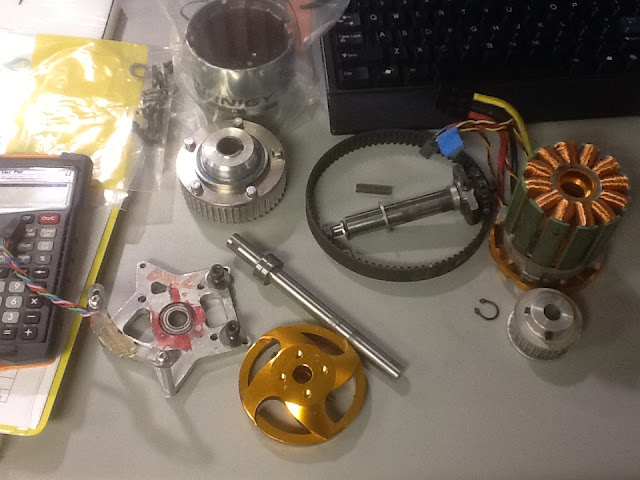
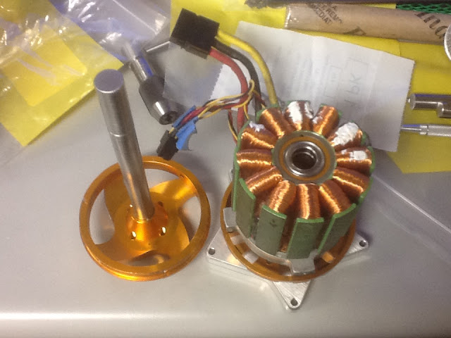
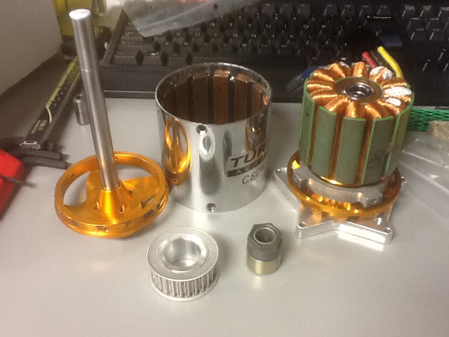
  • I have gotten a few new motors from Leader hobby, ready to rewind them
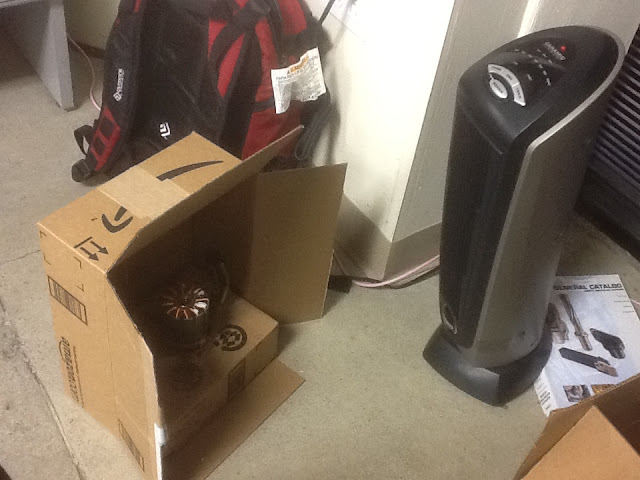
  • I have some promising air blowers coming in from ebay, and ideas about ducting, plenum shroud for the motor
  • For starters, I'll try to copy the success Thud has had on 18s using infineon 12fet controllers, modded and set up right. I have some other ideas that I might get to play with down the road.
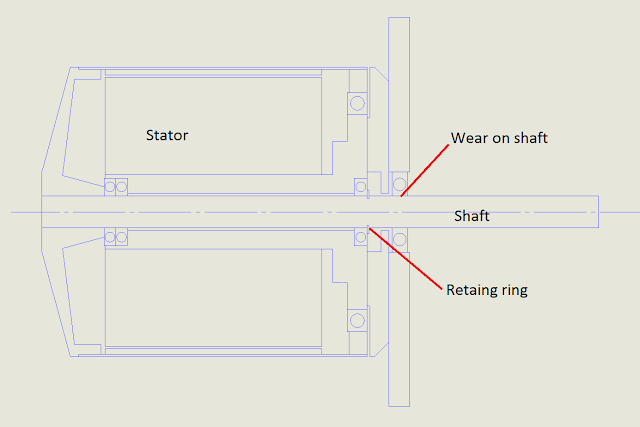
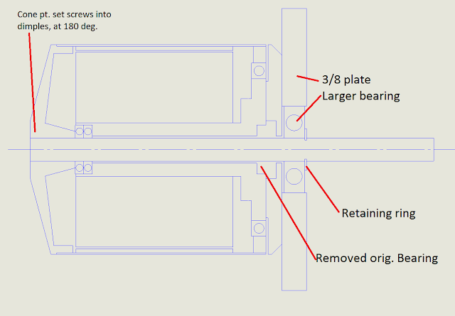
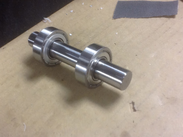
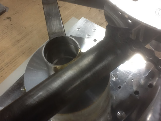
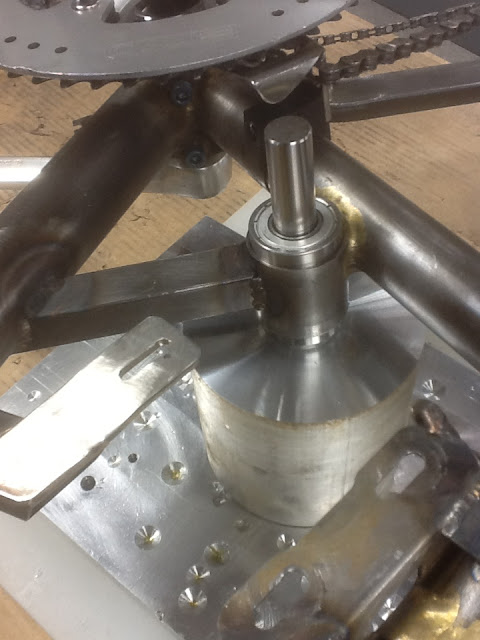
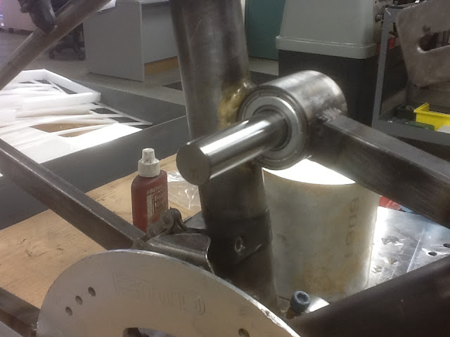
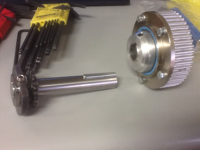
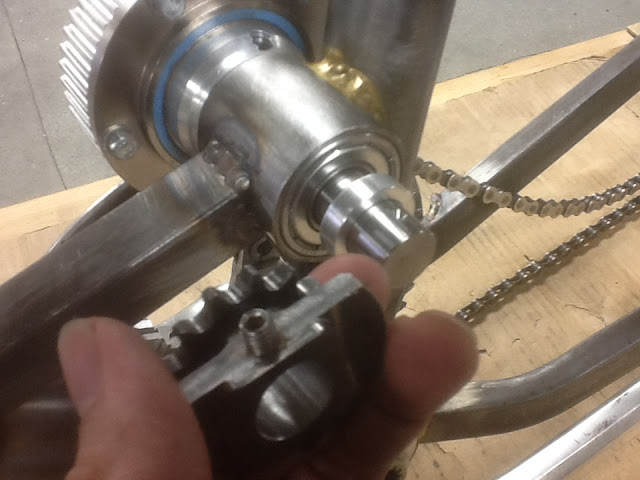
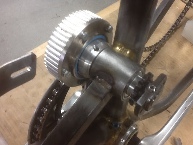
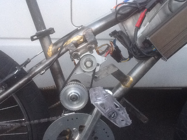
  • The current 2 stage drive system eats shafts and bearings up- unfortunately a bit fundamentally to some aspects of its construction. I've been thinking hard about how to redo it, which is the main matter of this post.

The options for redoing the drivetrain come down really to two options- making up a new timing belt 1st stage, chain final drive system- same architecture as currently- but set it up a bit "recumpence esque" with nice machined aluminum bits for tensioning and mounting the jackshaft. Option two is modifying the seat stays on the bike a bit and moving to a rear disc brake to do a single stage reduction, most likely with 219 chain.

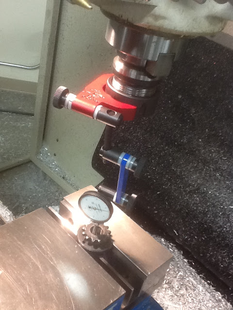
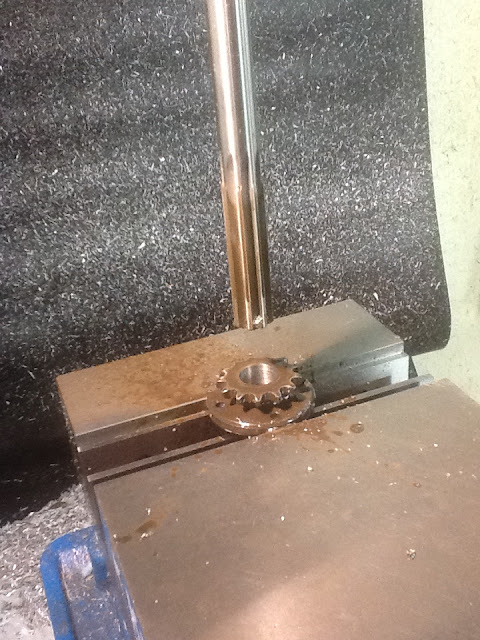
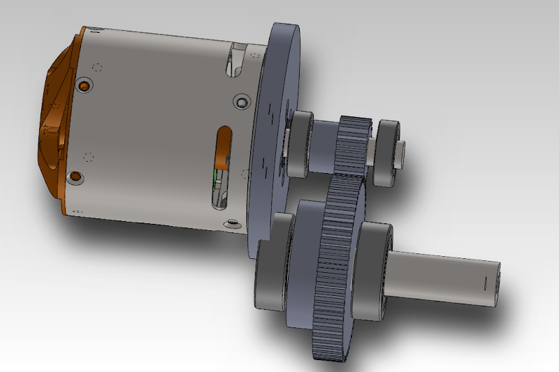
I was also toying a bit with building a spur-gear box first reduction but found just about every aspect of that project to just be kind of unreasonable, from attaching gears to shafts, to simply packaging it- it was looking like it was going to end up too wide to fit between the cranks. (I mean, it's definitely possible- just would take some serious resources work and time for custom shafts/splines/bearings/etc,etc,etc... This is modeled just with off the shelf gears, not optimal and frankly, not really workable at all)
gearbox.png


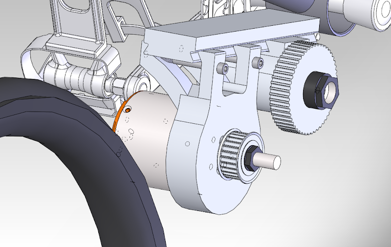
I then roughly modeled up a belt based drive with a novel feature- the motor and jackshaft move along a dovetail for tensioning- it was fun to think about in my head and I liked it for flexibility and because it's sort of something a machinist would think of :wink: but when I looked at it in the bike it just looks super fail bulky.
reduction.png


I then went and looked at pictures of Recumpence's davinci drive a bit more and thought about how nicely that design works- it's compact, rigid, and just about perfect for the application. I would copy it in a minute--- if it were at all even reasonable to adapt it to the face-mounted 80100 outrunner. Which it's not, very easily. I came to the conclusion after a lot of thought that it's just plain old very problematic to try to make up a reduction drive of any sort that is reasonably narrow to fit between the cranks, with this funny long, face mounting outrunner. By no means impossible, but not really going to be very elegant (like the davinci drive). I like elegant solutions.

Another idea I was working on at the same time was of making up a double freewheeling rear hub- Just made up a post here http://endless-sphere.com/forums/viewtopic.php?f=28&t=40661 - this would enable me to make up a huge sprocket and do a single stage reduction with 219 chain. Benefits being simplicity- potential reliability and efficiency- It would be a big chain for sure, moving awful fast. According to Thud the 80100 makes its best power if you can run it up to around 9krpm. That requires something like a 12 or 13 to 1 reduction ratio for the speeds I'm looking for (40-50 mph) - so, a rear sprocket in the 15-18" diameter range will be required. Making one up is no big deal- I have the tools. I in looking around a bit I haven't seen any completed drive systems set up like this, I'm wondering if anyone's got experience with how well the super large ratio single chain reduction works in practice, what the considerations must be.

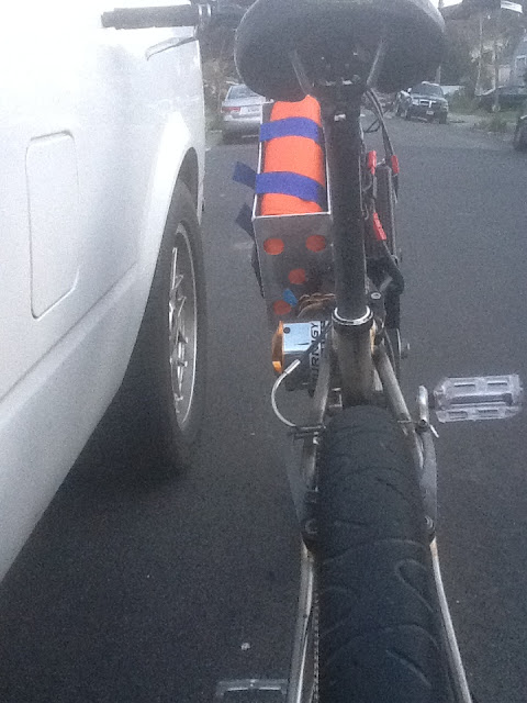
One other disadvantage to doing this would be that it would require modifying the right hand seat stay for better clearance, requiring moving to a rear disc brake instead of the rim brake that's on it now- this would be possible with the double right hand side freewheel hub setup ---

I'm certainly interested in hearing feedback or thoughts about these thoughts of mine. I've got to get started making up the bits as quick as I can, I've got a deadline of late August to quit working on it when school starts again! I'd like to shoot for racing it again in the October So-Cal race.
 
acuteaero said:
I came to the conclusion after a lot of thought that it's just plain old very problematic to try to make up a reduction drive of any sort that is reasonably narrow to fit between the cranks, with this funny long, face mounting outrunner.
This is how I got into custom motors.... You can start with the form factor.
 
Act,
If your planning a single speed drive set up... the single reduction is the way to go.
The added headach of making stay clearance for a "monster" sprocket is the only hang up on the set up...then its simple guides to keep the chain running where it should.
In regard to your geared reductions & cooling...all i will say is design for the simplest set up that will deliver the max return for the effort.

I am not a huge fan of air cooling...(rim-shot the pun!) the transfer of heat to air is kinda weak, & if you really fill a motor with copper you completely constrain the area for airflow. The presures required to get a meaningful CFM of air to flow through a motor is realy tough at this scale. But, I have been working on it.

I don't know if you saw my latest experiments for air cooling?(for the masses) I am winding in true LRK (6 out of 12teeth). Though not a copper doubling proposal that is possible, It is still yeilding an improvement in copper volume over the stock motors buy 25% ish. I think the stock motors put out an increable spread of power...so if we can triple the airflow through it, its a win.

The real benifit is the open teeth really have some room to move air through it (without un-achivable presures) as opposed to only the magnet gap.

Question: Is this bike for anything other than the race track?
 
If you're gonna use tubing you might as well use liquid, becuase you wont' get nearly the cooling from air that you would from liquid, partly due to flow rates vs surface area vs capacity of the media to accept and transfer heat.
 
Thud said:
Act,
If your planning a single speed drive set up... the single reduction is the way to go.
The added headach of making stay clearance for a "monster" sprocket is the only hang up on the set up...then its simple guides to keep the chain running where it should.
In regard to your geared reductions & cooling...all i will say is design for the simplest set up that will deliver the max return for the effort.

Thank you for this information- this makes me feel more confident moving forward with this plan- I will say, like I described above- it has seemed like the best idea so far. What do you like for chain guides? Idler tensioner to increase driver wrap? Soft plastic tubes? Dirtbike style plastic arch-shaped sliders? A guide to "feed" the chain onto the large rear sprocket?

I'm thinking the single stage 219 reduction shall be the plan for now- what size minimum front sprocket do you think is prudent to plan around? I'll have to get back on my CAD soon and start developing this plan.

Thud said:
I am not a huge fan of air cooling...(rim-shot the pun!) :lol: the transfer of heat to air is kinda weak, & if you really fill a motor with copper you completely constrain the area for airflow. The presures required to get a meaningful CFM of air to flow through a motor is realy tough at this scale. But, I have been working on it.

I don't know if you saw my latest experiments for air cooling?(for the masses) I am winding in true LRK (6 out of 12teeth). Though not a copper doubling proposal that is possible, It is still yeilding an improvement in copper volume over the stock motors buy 25% ish. I think the stock motors put out an increable spread of power...so if we can triple the airflow through it, its a win.

The real benifit is the open teeth really have some room to move air through it (without un-achivable presures) as opposed to only the magnet gap.

I had not seen your LRK wind and centrifugal fan cap until I just now. That is pretty dang cool. A bit of a hunch/question- With that LRK wind it seems you're also pretty much halving the amount of surface area of copper wire that's exposed to the air flow- I don't expect the steel laminations of the empty teeth to conduct heat away from the wound teeth (as a heatsink...) all that effectively. I wonder a bit if the tradeoff of less copper for more space is as advantageous as maybe a DLRK wind with smaller wire gauge for less fill/more space- if that would get you a better balance of low resistance, space for airflow and surface area to transfer the heat from... I'm kinda talking out my ass here, I don't really know enough to pass judgement.

On photos I've seen posted it looks like a cleanly done wind say a 6 turn with double 14ga wire (pretty good copper fill %) can end up with a little space between each tooth (assuming tidy terminations and external commutation sensors of course. More spacious than the stock config, for certain).

In the reading I've done around the forum it seems that the "best practice" approach is to maximize copper first to minimize heat, first- then do what you can to cool- I wonder where the point at which creating more heat in fact allows greater continuous average power because of increased cooling ability.

What is this unachievable pressure you mention? :) I have secured some gnarly blowers to play with and initial testing is pretty encouraging. This is a stock wound 80100 motor (where many of the teeth have no air space between them at all. Motor is straight out of the box, with skirt bearing etc.). The blower is an Ametek Minijammer 24v/5A unit. I found it on eBay. Rated ~45 CFM free air, ~.800 diameter outlet, ~12-18k rpm operational speed. BLDC motor, built in controller. It's a pretty sweet little unit, a steal at $35.

[youtube]uLv54AUAG3c[/youtube]
Thud said:
Question: Is this bike for anything other than the race track?

Between the blower, the chain and the motor this bike is going to be incredibly loud. I expect it will not be much fun to ride around town. I'm alright with that.
 
Have you tried running the blower:

A) with the motor running, to see how much airflow interference there is when the motor is spinning and disrupting the airflow even more?

B) with the blower *sucking* the air out of the motor instead of blowing into it, with the side cover hole of the blower mounted to the motor face? (because some blowers work way better and quieter sucking air than pushing it, and this would also decrease the length of the blower/motor assembly, assuming you aren't using a hose to move the air thru)
 
amberwolf said:
Have you tried running the blower:

A) with the motor running, to see how much airflow interference there is when the motor is spinning and disrupting the airflow even more?

B) with the blower *sucking* the air out of the motor instead of blowing into it, with the side cover hole of the blower mounted to the motor face? (because some blowers work way better and quieter sucking air than pushing it, and this would also decrease the length of the blower/motor assembly, assuming you aren't using a hose to move the air thru)

Thanks for the thoughts--- This test was just a very preliminary slap-dash one to get a rough qualitative feeling for approximately how much air the ametek blower might be able to push through the motor. Many variables will change, and I will test it again later to reassess its effectiveness- the real configuration will not have any cardboard or gaffa tape :wink:

The ametek blower will pull a bit of vacuum, but it'd designed to be used as a positive pressure generator- there are no specs or charts about the vacuum it creates- if the packaging constraints really favor that way I may consider it, but I think there should be no problem using it as a blower. The noise will be used to intimidate the other riders on track! They'll hear you coming!
 
hehe,
That definatly looks better than nothing... :p may as well duct a cooling vent for the controller. I recomend against haveing it sucking through & or blowing unfiltered anything into a motor...one tiny pebble or low flying bird will stop the motor in dramatic fasion. Just ask e-tard about the Willow springs race..he picked a tiny rock or metal shard & ended the day a couple laps into the main.
 
Back
Top