
I want to make a simple arduino based measurement of the phase current flowing to the motor but have some theoretical question. I am looking into this diagram of currents in the 3 phase bldc motor:
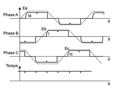
This shows that the so called "phase current" always flows over two phases either forward or backward. Since it's a sinewave controller the instantaneous current will go up and down in both directions. So if I take some hall effect current sensor and put in in phase B for example, measure the current over some period of 0.5 sec and calculate RMS from these values I will get the so called "phase current" as used by the bike simulator of Grin, right? Or 'm not correct?
I know that in the high end controllers there are 3 phase current probes but it's used for foc control and I just have to know how much torque is producing by the motor, nothing more.
