Photovoltaics not putting out enough amps.

captain387 said:
Apparently one panel was defective and was drawing down the rest of the panels.
It was the difference between the no load vs meter reading shorted amperage.
Try each panel separately with a load connected.

Good to know even a technician can get lost!

I'll try this, shorting each panel out one by one measuring the current, and retesting all the wiring. If I don't find any problems, I will short out the whole array down at the charge controller, and see if the amperage jumps.

thank you!
 
:wink: Unfortunately not a solar technician... I was a gas fitter that was in the area which was an hour away from the shop.

"Hey just swing by, and see if its something simple" At least I ruled out some the possibilities.

Good luck.
 
shawname said:
dak664 said:
I suspect when you say "shorting the panel" you mean bypassing the charge controller.

Actually I pulled one panel from the array and ran a lead between negative and positive, put it in full sun, and measured the amps. The panel put out close to it's rated amps.
shawname: I'm confused, I still don't understand what you mean by "shorting". Sounds like you connect the panel positive lead to the panel negative lead, correct? If so, the voltage would immediate drop from 17.5V to almost 0V. Since the panel provides a relatively constant power (watt), dropping the voltage (V) causes the current (A) to rise, which is what you were reporting (2.9A). But that current is not meaningful because the voltage is unknown. So what is the corresponding voltage?
 
[/quote]
shawname: I'm confused, I still don't understand what you mean by "shorting". Sounds like you connect the panel positive lead to the panel negative lead, correct? If so, the voltage would immediate drop from 17.5V to almost 0V. Since the panel provides a relatively constant power (watt), dropping the voltage (V) causes the current (A) to rise, which is what you were reporting (2.9A). But that current is not meaningful because the voltage is unknown. So what is the corresponding voltage?[/quote]

You are right, since I was having problems with amps not volts I just measured amps. My assumption was that the voltage would be 17 because the pane was rated at 17V, 2.9 amps. So I will also measure volts.
 
I am making progress. I checked the charge condition of my battery array and found one battery flat. This could have been what was making my inverter shut down due to low voltage, especially as it was the last battery in the parallel. I am charging it up now from house current. My other two battery arrays were fully charged at 14.7 volts.

This tells me that :oops: the charge controllers were doing their job and reducing the amount of current that they were using, hence my low readings.

Also when I disconnected the leads from each of the arrays at the charge controllers, and shorted them, connected the negative and positive together, the amps jumped.

However one of my arrays has an interesting phenomenon. The voltage reads 17.8, and when shorted, the current reads 12 amps, but the positive charge of the current is in the negative lead! Hmmm.

By the way, I shorted the full arrays in the early morning today with way less than full light. :wink:
 
shawname said:
SamTexas said:
shawname: I'm confused, I still don't understand what you mean by "shorting". Sounds like you connect the panel positive lead to the panel negative lead, correct? If so, the voltage would immediate drop from 17.5V to almost 0V. Since the panel provides a relatively constant power (watt), dropping the voltage (V) causes the current (A) to rise, which is what you were reporting (2.9A). But that current is not meaningful because the voltage is unknown. So what is the corresponding voltage?

You are right, since I was having problems with amps not volts I just measured amps. My assumption was that the voltage would be 17 because the pane was rated at 17V, 2.9 amps. So I will also measure volts.
You're welcome. Looking forward to seeing the measured "shorted" voltage. I'm pretty sure it'll be 0V.

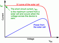
Here's the reference: http://www.pveducation.org/pvcdrom/solar-cell-operation/short-circuit-current
IV-ISC.gif
 
SamTexas said:
Looking forward to seeing the measured "shorted" voltage. I'm pretty sure it'll be 0V.

Sam,

You are entirely right. The unloaded voltage was 18.5, no amps. When I shorted the panel and measured the amps, I got 2.2 amps, (cloudy) and 0 volts!

I had always thought that the panels wattage was measured by (shorted out amps) X (loaded volts.) That makes sense, doesn't it? It is revealing how my (untested) assumption led me astray. I think that's why I like problem solving. Because you are always testing the accuracy of your thinking against something that doesn't lie- the real world.

Yet your graph shows that the voltage can climb while not affecting the current- to a certain point- giving you a sweet spot of maximum yield- that can only be optimally harvested with a MPPT charge controller, correct?
 
shawname said:
I had always thought that the panels wattage was measured by (shorted out amps) X (loaded volts.) That makes sense, doesn't it?
Not really. If both voltage and current are non-zero numbers then their products is also a non-zero number meaning that energy is actually flowing through the shorted circuit meaning that the wire will get hot, will melt in order to "UNshort" the circuit.

shawname said:
Yet your graph shows that the voltage can climb while not affecting the current- to a certain point- giving you a sweet spot of maximum yield- that can only be optimally harvested with a MPPT charge controller, correct?
It's not my graph, but I think you're right about the sweet spot. I don't have an MPPT controller so I can't say for sure.
 
shawname said:
Yet your graph shows that the voltage can climb while not affecting the current- to a certain point- giving you a sweet spot of maximum yield- that can only be optimally harvested with a MPPT charge controller, correct?
Not exactly, since charging is about total coulombs transferred and not power. Fastest charge is with the most amps put through the battery, and the most amps are always at the lowest volts that are enough to active the reverse chemistry, but a direct connection will draw the panel down to the battery voltage, always the maximum current but probably not near the maximum power point. A buck converter, controlled by feedback that gives the most current through a shunt, will increase the current beyond that by temporarily storing excess voltage in a magnetic field and then slowly releasing it to augment the current, at KHz rates. Historically the panels are sized around 18 volts to provide enough voltage in summer for 12 volt battery charging; in winter the panel voltage can go up to 21 volts. The excess power used to be wasted, but buck converter charge controllers are nowadays almost as cheap as PWM charge controllers.

Or if the panel voltage were less than the battery, a boost converter would do pretty much the same thing as a buck converter, in this case swapping excess current to the magnetic field, and the diode that activates the magnetic field drawdown is reversed.

Combine the two with some firmware search algorithm and you would have a much more expensive MPPT controller, which could then also handle the case of a motor or other inductive load where maximum current is not necessarily maximum power. But not needed for battery charging.
 
Most Mppt controlers allow running a higher voltage say 60 v to charge a 12v battery system. If yours will allow this then consider putting your panels in SERIES and program the charge controller properly. A big advantage is a greatly reduced energy loss in the wiring going from the panels to the charge controller.
 
Thanks Dak664 for your xlnt explanation. Can you answer a few questions??

dak664 said:
but a direct connection will draw the panel down to the battery voltage

Why is that? It seems that current would flow from the higher voltage of the panels to the batteries. Is it because the panels see the batteries as a direct short?

dak664 said:
by temporarily storing excess voltage in a magnetic field and then slowly releasing it to augment the current, at KHz rates

Would the magnetic field be a coil or a capacitor? It would seem like either of those would be able to handle quick fluctuations, but not fluctuations over the course of an hour. The KHz rates would allow for less amps, lighter circuitry?

dak664 said:
A buck converter, controlled by feedback that gives the most current through a shunt

The shunt being a small resistor in parallel?

Sorry, about the newby to electronics questions! :)
 
shawname said:
Why is that? It seems that current would flow from the higher voltage of the panels to the batteries. Is it because the panels see the batteries as a direct short?
Light pushes a fixed number of electrons through a nominal 0.5 volt potential barrier in each cell, or 18 volts in a 36 cell panel. Each electron has excess energy depending on the wavelength of the photon causing the push, that excess is dissipated within the cell on the high side of the barrier. With no load the small capacitance of the circuit will charge up to 18 volts, now the electrons have enough energy to fall back through the barrier and the current recirculates in each cell. Connect a 12 volt battery and that capacitance will quickly discharge to 12 volts, and the voltage across each PV cell will drop to 0.33 volts. The original current will begin to flow, but another 0.17 volts of energy is lost on the high side of the barrier (actually the current increases a little because the lower barrier allows longer wavelength photons to be effective).

shawname said:
Would the magnetic field be a coil or a capacitor? It would seem like either of those would be able to handle quick fluctuations, but not fluctuations over the course of an hour. The KHz rates would allow for less amps, lighter circuitry?
A coil in series will continue to push electrons when the panel is disconnected, the collapsing field going to zero and generating whatever voltage is needed to drive current through the battery. The voltage across a capacitor would be decreasing so it would only provide current for a short time, until the voltage drops to battery equilibrium potential.


shawname said:
The shunt being a small resistor in parallel?
In series, to measure the current through the battery. For most battery chemistries the voltage always increases with increasing current (not NiMH however) so a feedback loop that maximizes the voltage would work as well. But small changes in voltage would represent large changes in current, and higher precision ADCs would be needed to measure it. For less than 10 amps or so the watts lost across a < 1 ohm shunt are not important; for kWh battery banks it might make sense to measure voltage instead, or use a Hall device to measure the current.
 
dak664 said:
With no load the small capacitance of the circuit will charge up to 18 volts, now the electrons have enough energy to fall back through the barrier and the current recirculates in each cell. Connect a 12 volt battery and that capacitance will quickly discharge to 12 volts, and the voltage across each PV cell will drop to 0.33 volts.

Ahh, so photocells behave as capacitors. That helps me to understand.

Dak, I dont' understand musch of what you wrote, sorry. Thanks for your explanations, and I'm sorry that they were beyond my education.

Shawn
 
Back
Top