chuyskywalker
10 kW
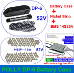
I'm working on a build where I'm going to put a 14s5p 18650 Molicel p26a battery together in a Polly DP-6 case.

This case has just enough space for the cells, the necessary wiring, and a small 35A separate port, key switch enabled, bms. The pack, though, is capable of pushing up to 125-175A (5x25-35A each cell) with those cells, and I'd like to take advantage of that (really, only about 100A), yet I don't want to lose the BMS safety features. Problem is, a capable 100+A BMS will not fit in this case.
I believe I can maintain the same relative safety, though, using a feature that a few controllers come with: the "ignite" (or key switch) on the controller itself. This feature has the controller pass battery positive out a small gauge wire and expects the voltage to return on the "ignite" wire. This is typically used both as a way to signal the controller to turn on, but also to get one of those half-twist throttles with voltage display and key switch combos to work up at the handle bars.
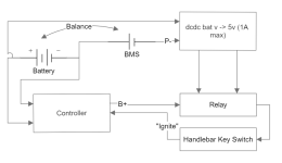
Here's what I propose:

(Yeah, my diagram is decidedly NOT electrical engineer accurate, oh well!)
On the battery pack case, it has 5 pins. I'll use pins 1&2 for positive and 4&5 for direct negative. These will route to the controller directly. Internally, the BMS will be wired up as normal but the P-, instead of supplying the negative for the pins on the case, will connect to pin 3 only. Pin 3 from the cradle will then be routed, along with a split off the positive pins, to a DCDC convert to get me down to a workable relay range. This relay, along with a key switch, will interrupt the "ignite" wire circuit.
In this fashion:
Have I missed anything? Is something going to blow up in my face here?

This case has just enough space for the cells, the necessary wiring, and a small 35A separate port, key switch enabled, bms. The pack, though, is capable of pushing up to 125-175A (5x25-35A each cell) with those cells, and I'd like to take advantage of that (really, only about 100A), yet I don't want to lose the BMS safety features. Problem is, a capable 100+A BMS will not fit in this case.
I believe I can maintain the same relative safety, though, using a feature that a few controllers come with: the "ignite" (or key switch) on the controller itself. This feature has the controller pass battery positive out a small gauge wire and expects the voltage to return on the "ignite" wire. This is typically used both as a way to signal the controller to turn on, but also to get one of those half-twist throttles with voltage display and key switch combos to work up at the handle bars.
Here's what I propose:

(Yeah, my diagram is decidedly NOT electrical engineer accurate, oh well!)
On the battery pack case, it has 5 pins. I'll use pins 1&2 for positive and 4&5 for direct negative. These will route to the controller directly. Internally, the BMS will be wired up as normal but the P-, instead of supplying the negative for the pins on the case, will connect to pin 3 only. Pin 3 from the cradle will then be routed, along with a split off the positive pins, to a DCDC convert to get me down to a workable relay range. This relay, along with a key switch, will interrupt the "ignite" wire circuit.
In this fashion:
- If the BMS goes into LVC/HVC for all or even a single group, the P- cuts off, the relay closes, and the controller turns off
- If the BMS switch is turned off, the P- cuts and the controller is offed
- If the key switch is disconnected, the controller is off
- The overall physical size of this setup is very small (the dcdc and relay are tiny, especially compared to a contactor of this size)
Have I missed anything? Is something going to blow up in my face here?

