

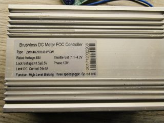
Hello, I'd like to try a new controller for my electric bike. I've attached a photo of the label on the unit I want to use below.
I see empty connection points on the circuit board; I want to know what they are. It seems like there are abbreviations for some terms written for each connection point... For example, L, H, DC, XS, XZ, DZ, CZ, YJ, YJT, FD or FO, ZZ, YY and SS.
When I measure these points on the board:
L = 3.1 volts
H = 0 volts ?
DC = 3.1 volts ?
XS = 3.3 volts ?
XZ = 3.3 volts ?
DZ = 0 volts ?
CZ = 0 volts ?
YJ = 0...3 volts (continuously variable) ?
YTJ = 3.3 volts ?
FD or FO = 3.3 volts ?
ZZ = 3.3 volts ?
YY = 3.3 volts ?
SS = 3.3 volts
Here are the parts I've identified:
When I short-circuit the pad marked "L" to GND, the motor stops. When I disconnect it from GND, it starts spinning again, so I assumed this is the brake lever connection.
When I short-circuit the pad marked "SS" to GND and then release it, the motor speed increases by one step; there are a total of 3 different speed bands, so I assumed this is the gear shifter.
When I connect the pad marked "DC" to GND and disconnect it while the motor is spinning, the motor stops and doesn't spin again unless I release the throttle and turn it again. However, I couldn't understand its purpose.
When I connect the pad marked "FD" or "FO" to GND while the motor is spinning, it stops. When I disconnect it, it waits for 1-2 seconds and then starts spinning again. I couldn't understand what it does.
I couldn't find the function of the pins marked H, XS, XZ, DZ, CZ, YJ, YJT, ZZ, YY. If you know, I would be grateful if you could let me know.
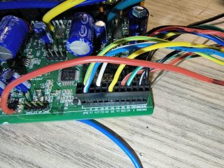
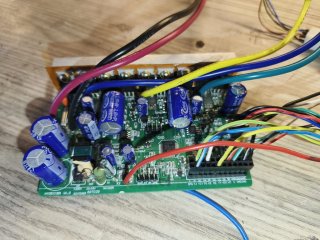
I see empty connection points on the circuit board; I want to know what they are. It seems like there are abbreviations for some terms written for each connection point... For example, L, H, DC, XS, XZ, DZ, CZ, YJ, YJT, FD or FO, ZZ, YY and SS.
When I measure these points on the board:
L = 3.1 volts
H = 0 volts ?
DC = 3.1 volts ?
XS = 3.3 volts ?
XZ = 3.3 volts ?
DZ = 0 volts ?
CZ = 0 volts ?
YJ = 0...3 volts (continuously variable) ?
YTJ = 3.3 volts ?
FD or FO = 3.3 volts ?
ZZ = 3.3 volts ?
YY = 3.3 volts ?
SS = 3.3 volts
Here are the parts I've identified:
When I short-circuit the pad marked "L" to GND, the motor stops. When I disconnect it from GND, it starts spinning again, so I assumed this is the brake lever connection.
When I short-circuit the pad marked "SS" to GND and then release it, the motor speed increases by one step; there are a total of 3 different speed bands, so I assumed this is the gear shifter.
When I connect the pad marked "DC" to GND and disconnect it while the motor is spinning, the motor stops and doesn't spin again unless I release the throttle and turn it again. However, I couldn't understand its purpose.
When I connect the pad marked "FD" or "FO" to GND while the motor is spinning, it stops. When I disconnect it, it waits for 1-2 seconds and then starts spinning again. I couldn't understand what it does.
I couldn't find the function of the pins marked H, XS, XZ, DZ, CZ, YJ, YJT, ZZ, YY. If you know, I would be grateful if you could let me know.