Ping Battery Elective Surgery

outbackhack

10 mW
Joined
Feb 9, 2012
Messages
30
Location
Washington DC, USA
Thinking of taking the plunge and attempting to split one of my Ping batteries in half for v2.0 of my ebike. I want to keep the battery almost entirely in the front-triangle, but this time keep it narrow enough (4" instead of 6") that I can pedal comfortably and the only way to do that is going to require breaking the pack in half.

I removed the shrink wrap and sized up the task last night. Before I start cutting&soldering I wanted to see if anyone here who has experience with this packs can confirm I am cutting in the right place and approaching the task correctly.

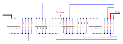
Here is my pack, how I believe it is configured, and where I am planning to cut. My plan is to use a dremel with a thin cutting wheel to divide the board joining groups 4 & 5, solder 1m of 10g wire to reconnect 4 & 5, and then repack the cells into 2 separate enclosures.

2012 Ping v2.5 48v 20ah (2x 8s4p 5000mah lifepo4)
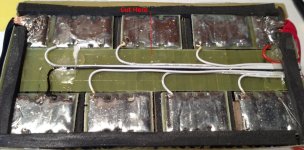
pack2.JPG
pack.png
 
the way i do it is to use a soldering iron or two and put the battery on the side over the edge of the table and melt and sweep the solder off the pcb where you have your line (solder falls onto some newspaper on the floor) so you can see and unsolder the tabs where they fold over. cutting here will cut the tabs in two. bad.

when the solder is gone, and while you hold the soldering iron on that spot, pick up the tab, (with a hooked pick or one end of the two soldering irons), that is folded down onto the pcb there and stand the tab up vertically from the pcb, and do the same for the tab from the other cell that is underneath it.

when each cell has been separated at those end tabs, you can just cut the little bit of pcb alongside the edges of the slot the tabs are standing up in. then the two sections of the battery are isolated from each other, and you can fold the tabs back over into the solder when you solder your jumper cable on there.

when the two pieces of the connector are separated, you can disassemble the pack. remove all the tape and put 1/8" hardboard plates on the ends and then put the tape around those plates. so the ends of the pouches are all compressed uniformly because the tape distorts and damages the corners of the pouches as they swell over time.

for 2M you wanna use something more than a single 10AWG, two minimum, and you have to put the sense wire for the lower cell, #4 in the middle of the 10G jumper so the delta V across the length of jumper is split between the #4 and #5 cell but they will both be the source of your LVC shut downs anyway.
 
Sounds like a good method to me. Removing some solder would make the cut less tricky. Looks like you have identified the spot to cut. Just be extremely carefull you don't nick the pouches with that dremel. One slip, the wheel sucks into the cut and goes way deeper.

Wrap it really tight again with strapping tape when you get it done.
 
Thanks for the tip about removing some solder, I didn't think there was a tab folded over in the middle of the board but after looking more closely it looks like there is one or more there. Was able to melt and remove a little of the solder last night, but I don't think my 40w iron is up to the task of quickly melting that quantity of solder. Looks like I need to upgrade to a tool that can heat the load of solder more quickly so there is less time for the heat to soak into the cells.

Another interesting bit I noticed last night is that it appears the cells are already individual taped into 2 groups inside the hard outer shell. Hopefully that will make it easier for me once I get the tabs unsoldered.
 
yes, ping wraps 4 cells at a time into sections with some plastic wrap around them.

it does take two soldering irons to keep the tabs hot enuff to pick them up out of the solder. otherwise the solder that holds the tabs onto the little pcb will remain solid and not release the tabs end so you can hook it and stand it up. once you can get that section hot enuff, the solder just runs off and falls unto the newspaper under the edge of the table. save the solder and reuse it to connect the big doubled up 10G jumper wire.

you can just cut the little 2mm section on each side of the slot and a little more heat from the soldering irons releases the tabs and pcb connector from each other if they are still stuck.

use diagonal cutters, dikes, to cut the little bit of pcb at the edge of the slots.

remember you have to attach the sense wire in the middle of the jumper.
 
NOt trying to hijack this thread but i am going to replace the battery cells on my A2B metro...Like for Like. 3.7v li-ion cell sanyo 18650 1500mah battery 70 cells per battery pack. The pack is a plastic molded affair that slides into the downtube, so i don't want to get creative with another battery cell design.

http://www.alibaba.com/product-gs/687392537/hottest_sell_3_7v_li_ion.html

Can you recommend the best type of solder for this?
Any suggestions on how best to do this?

thanks!
 
So the procedure initially seemed like a success, but a problem has cropped up now after charging,balancing,lightly discharging the pack. The 4p cell groups (4&5) on either side of the split are charging faster than the rest of the pack, hitting 3.8-3.9v before the charger shuts down. The BMS brings them back down to 3.6v along with the rest of the pack eventually, but the next charge cycle sends them both back up to nearly 4v. The 8 gauge bridge between cells is 24" long with the balance wire for the group crimped near the midpoint of the bridge wire.

I'm trying to figure out the cause for the overcharging of these both groups, my best theory is that one cell in each group was damaged somehow when I separated them, reducing their capacity and causing them to peak before the rest of the pack. However I'm pretty sure the separation was done cleanly without damaging any tabs and it's interesting that both groups a short the same symptoms +/- 0.05v. But if this is the case and the damaged groups are now closer to 15ah instead of 20ah, then they wont have enough capacity to complete my daily commute.

Any chance I'm wrong about this and the pack can be salvaged without having to cut it up further and replace cells?

Attached a picture showing the sequence of the whole pack lighting up to balance with group 4 & 5 taking longer to come down before all the lights finally go out.

bms.jpg
 
but they all got above about 3.65V? then after you took it off the charger these cells stayed lit longer? i don't think there is anything wrong.

if you wanna test the capacity so you feel like and actually do know more about it than now i can walk you through the steps to do a bench test to establish the capacity of most of the cells. it is good thing to know so when you test it later you can tell if the pack is losing capacity somewhere.

also the v2.5 signalb will turn the charging fet back on when the high cell drops to 3.8V, not 3.6.

the leds turn off when the shunt transistors drain them all down to 3.6-3.61V. then the led drains it down the remainder from what i have seen. you can measure it while it flickers. it comes back on briefly because the current through the led causes a voltage drop that turns it off and when the current stops the voltage builds up again just a little and then the led ignites and drains that voltage, and this cycle goes on until there is not enuff voltage left to ignite the led.
 
Correct, all 16 groups get above 3.65v and the BMS brings all the higher ones back down to around 3.6v.

Before I made the modification last week it was a very balanced pack with about 70 cycles. My concern is that the cells are briefly getting up to 3.95v-4.0v which I believe is too high for lifepo4 cells. Also it seems odd that the same 2 groups of cells keep peaking +0.4v above the others which are all +/-0.05v after being balanced and lightly discharged (0.1ah) .

I'll attempt a deeper discharge tomorrow after letting the BMS balance the pack awhile hooked up to the charger and see if the 2 suspect groups appear to drop off in voltage before the rest of the pack.
 
why are they suspect if they hold the charge voltage longer than the other cells?

to my logic they are in better shape than the others if they do not leak down fast so i am not sure i understand your logic in this entire analysis.
 
Back
Top