Hi,
I’m trying to diagnose a smart BMS from a 48 V / 13S battery used in a 2026 Momas e-bike.
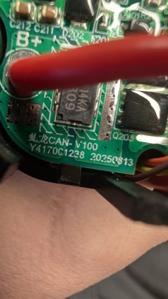
The PCB is marked:
虬龙 CAN-V100
Y4170C1238
20250813
The battery originally arrived deeply discharged at approximately 38.6 V. At that point the raw cell stack had voltage, but the BMS main output was 0 V.
I charged the 13S cell stack directly and monitored every series group. The groups are very well balanced. After raising the pack voltage, the BMS recovered and the normal discharge output became active again.
I have now charged the pack to approximately 53.5 V, but the original charger still does not actually charge the battery.
The charger has three wires:
Red – power +
Black – ground / power −
Yellow – communication/signal
The charger normally stays green. When connected, the battery detects it, wakes up and the battery LED indicator behaves as if charging has been detected, but no charging current flows.
On the yellow wire I measure approximately 11 V relative to black/ground.
I scoped the yellow wire. There is clearly repeating digital communication. With the battery disconnected I see only short communication bursts. As soon as the battery is connected, additional much longer data bursts appear. Therefore there appears to be an active charger/BMS handshake, but the charger never enables power delivery.
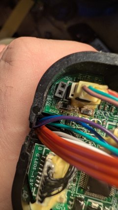
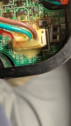
The PCB has a connector marked J501 and markings including CH / CL / SH around the communication section.
There are also two visibly heat-discoloured components around R561 / R562 close to this connector. I measured approximately 10.9–11 kΩ in circuit on them. My next step is to trace the yellow communication wire through this section.
The PCB also has G / RESET pads. Briefly bridging G and RESET causes the BMS to restart, but charging is still not enabled.
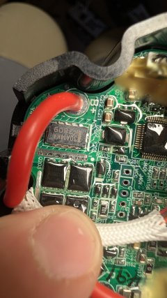
There is also a power component marked:
30A14KA
K2809
I have not been able to find reliable documentation for the CAN-V100 PCB or identify the charger communication protocol.
Does anyone recognize this Qiulong (虬龙) CAN-V100 BMS?
I’m particularly looking for information about:
CAN-V100 pinout or schematic
charger communication protocol
CH / CL / SH pin functions
charging MOS enable/fault behaviour
service/reset procedure
diagnostic/software interface
function/value of R561/R562
identification of the 30A14KA K2809 component
I have high-resolution photos of both sides of the PCB and oscilloscope captures of the charger communication and can provide any additional measurements.
Thanks for any information.
I’m trying to diagnose a smart BMS from a 48 V / 13S battery used in a 2026 Momas e-bike.
The PCB is marked:
虬龙 CAN-V100
Y4170C1238
20250813
The battery originally arrived deeply discharged at approximately 38.6 V. At that point the raw cell stack had voltage, but the BMS main output was 0 V.
I charged the 13S cell stack directly and monitored every series group. The groups are very well balanced. After raising the pack voltage, the BMS recovered and the normal discharge output became active again.
I have now charged the pack to approximately 53.5 V, but the original charger still does not actually charge the battery.
The charger has three wires:
Red – power +
Black – ground / power −
Yellow – communication/signal
The charger normally stays green. When connected, the battery detects it, wakes up and the battery LED indicator behaves as if charging has been detected, but no charging current flows.
On the yellow wire I measure approximately 11 V relative to black/ground.
I scoped the yellow wire. There is clearly repeating digital communication. With the battery disconnected I see only short communication bursts. As soon as the battery is connected, additional much longer data bursts appear. Therefore there appears to be an active charger/BMS handshake, but the charger never enables power delivery.
The PCB has a connector marked J501 and markings including CH / CL / SH around the communication section.
There are also two visibly heat-discoloured components around R561 / R562 close to this connector. I measured approximately 10.9–11 kΩ in circuit on them. My next step is to trace the yellow communication wire through this section.
The PCB also has G / RESET pads. Briefly bridging G and RESET causes the BMS to restart, but charging is still not enabled.
There is also a power component marked:
30A14KA
K2809
I have not been able to find reliable documentation for the CAN-V100 PCB or identify the charger communication protocol.
Does anyone recognize this Qiulong (虬龙) CAN-V100 BMS?
I’m particularly looking for information about:
CAN-V100 pinout or schematic
charger communication protocol
CH / CL / SH pin functions
charging MOS enable/fault behaviour
service/reset procedure
diagnostic/software interface
function/value of R561/R562
identification of the 30A14KA K2809 component
I have high-resolution photos of both sides of the PCB and oscilloscope captures of the charger communication and can provide any additional measurements.
Thanks for any information.