QS 3000 138 motor bike installation generalized

Brilliant effort, and I appreciate the documentation.

I am no safety nanny (*and I have the fresh scars to prove it), but...for the younger new readers...

The sprocket thinning jig with drill power and angle-grinder to face the sprocket is very clever. That being said, please wear eye protection. I still have ten fingers, but if I damaged one beyond healing, I'd still be able to continue my work.

My eyes? I do not risk them because after a couple of close calls, I pondered my life with only one eye. Since I hate having to search for protective equipment, I have a set of safety hlasses at each piece of equipment so its always by the start button.
 
Spinningmagnets,

Good point about safety glasses being a must. Since the posting of employing a die grinder for sprocket size reduction, I feel that die grinder swarf contamination( from hardened steels)is too hazardous to warrant the use of this tool for sprocket grinding. Further more a somewhat safer method is readily useable.

The swarf fibers of die grinding could easily be transported from from one's fingers to one's eyes if you happened to rub "an itch?" near an eye. Safety glasses do not stop one from rubing areas near an eye.

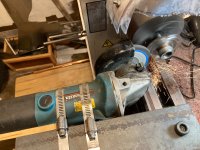
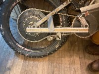
I have since tested the material removal using grinder with a grinding wheel and slim wheels. The grinding wheel does the job quicker.

IMG_1241.JPG

Hence my suggestion: use a right angle grinder not a die grinder/carbide deburring tool to remove steel from motor cogs.
 
I agree on all points presented. This picture is gold. A drill is not a lathe, and a spinning abrasive disc is not a carbide cutting tool, but...

There is much that can be done in a home garage with basic affordable tools. Thanks again for posting this
 
Is a Short Chain Snubbing Your Rear Suspension Travel?

The QS 3000 motor when bike mounted does fine as a one speed. Hopefully your QS3000 mount is on a full suspensions bike? Big deraillleurs can handle some 18 chain links of slack -- about 9". If you have kept the OEM derailleur in use for chain slack you likely are not snubbing full suspension motion. It is when you ride off trail that derailleurs get torn off or severely bent necessating a substitute chain slack remover. Most mtn bike trails are too well groomed for a derailleur snag. Dirtbike trails are poorly groomed by mtn bike standards.

Probably for most mtn bike rear suspension systems the minimun chain length changes as the rear axle travels about the BB axle.The BB concentric suspension systems like on a Kona Stinky do not change minimun chain length as the swingarm rotates about the BB axle. This feature has no anti sag so during starts you get a sag or unweighting when throttling -- less normal force on rear tire -- traction? If you do not have concentric rotation suspension and have removed the derailleur you will need a chain tensioner to keep an almost snug chain on an edirtbike.
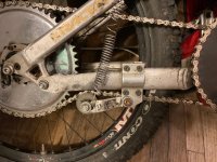
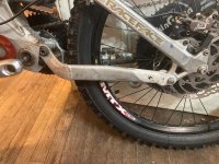
IMG_1529.jpg

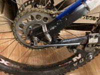
In the above photo the chain may appear to be almost rubbing the bottom of the lower stay. It's actual pathway is behind the lower stay.

These single pulley chain tensioners for keeping a chain on line with the rear sprocket work best when placed very close or next to the rear sprocket. Their main drawback is they can handle effectively a max of about 1 1/2 links of chain slack when used on severely bouncy terrain. Further more this arm attachment location will cause the swing arm action to bump the lower stay if there are about 2 links of chain slack.

Wider chains do stay on better than a narrower ones of the same pitch. Likely a minimum size chain for the QS 3000 is #415H chain or the motorcycle versions of this chain. The chain slack problem is further compounded because there are no half links for this chain. As a sideline issue, half links make more noise than regular link connections.

If you do not have enough chain slack for your suspension, then the chain at some point in suspension travel will get tight. Once tight, the chain is not rigid but acts as a stiffer spring than your suspension would normally have if there were slack. The chain as a spring is not likely to break but it does pull on the BB axle and, if you have a standard 5/8" square end shaft, a one time Big Air drop could bend the axle very slightly causing a wobble or out-of-plane rotation for the double flange BB hub -- more noise from the cyclic loosening and tightening of the chain generating warbling noise cadences.

The minimum amount of chain slack in the system will make for a much higher likelihood of the chain staying on the sprockets. More on how to measure and optimize chain slack next post(s).
 
DingusMcGee said:
Spinningmagnets,

Good point about safety glasses being a must. Since the posting of employing a die grinder for sprocket size reduction, I feel that die grinder swarf contamination( from hardened steels)is too hazardous to warrant the use of this tool for sprocket grinding. Further more a somewhat safer method is readily useable.

The swarf fibers of die grinding could easily be transported from from one's fingers to one's eyes if you happened to rub "an itch?" near an eye. Safety glasses do not stop one from rubing areas near an eye.
...
I'd be more worried about the bloody things being transported through the air to the lathe bed! Always cover the bed whenever any kind of abrasives are near it, that crap gets between the slides and becomes grinding paste.

If that grinder snatches, what's going to happen? Can't see from the pic if it's supported underneath, if it can kick into the workpiece then there's a high chance you'll get to see a disk explosion close up, wouldn't recommend (I always try to mount using the threaded front handle mounts, both if possible). I can't preach to anyone on correct use of tools but things like grinders and chainsaws can be highly concentrated evil if mishandled, only scars for life if you're lucky.
 
Hi stan.distortion,

There are two kinds of cuttings created depending on the cutting tool. The die grinder when grinding carbon steels using carbide bits produces mostly metal filings whereas a grinding wheel introduces steel swarf and abrasive silicate chunks and/or other abrasives. A magnet picks up die grinder cuttings of carbon steel. The amount of tungsten carbide coming off the tools is miniscule. So yes the silicate abrasive fragments need containment/removal for tool longevity, but in no way are silicates on a lathe bed as harmful when transferred to people as metal die grinder cuttings are to people.

The probem with a cloth under a powerful grinder employing an abrasive wheel is the cloth catching on fire from the grinder sparks heating the cloth to combustion temperatures. Maybe a vacuum would be fine?

When using a grinder attached like I show there is very little motion of the carriage and crossfeed. Any advancing motions of the grinder are much more carefully controlled/constrained than holding a grinder freehand while doing this task. A gear clamp is good for some 300lbs at very little deflection -- 2 are used here. 300 lbs of anti torquing force is somewhat more than a person could manage on short notice. I suppose for redundancy of attachment I could also attach a tang from the threaded handle hole to the angle iron bridge? The grinder fastening method seems quite adequate to me but what mode of failure are you suggesting when you say "grinder snags"? More detail is needed on how this proposed snag begins and progresses to start such a hurling situation -- maybe a meteriorite hits the grinder and breaks a clamp? The sprocket surface is and remains quite smooth during this operation.

Thanks for bringing the contaminant to my attention.
 
Yeah, the swarf from burrs is vicious stuff! I'll normally put a sheet of plywood, steel, whatever is to hand over the bed if grinding, best avoided altogether imo but there's sometimes no alternative. The extra rigidity is the big danger when fixing a grinder to a lathe, if things do go wrong for any reason then there's no-where for them to go, they're stuck between two immovable objects so something has to give and the wheel or disk spinning at 10k rpm is the weakest link... it can go from good to ugly in an instant.

Doesn't necessarily need to be the kind of snatch you get when using them by hand and the disk digs in hard, vibration is enough, chatter. It's not something I can really offer any advice on other than "don't try this at home" but I'll always try to keep the inclination of any movement in the mounting arrangement away from the cut, if things snatch for any reason the disk will pull away from getting trapped rather than try to dig in deeper.
 
Stan.distortion,

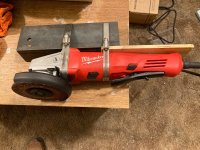
Here is a pic of the grinder bridge with an 11 amp grinder now attached:

IMG_1530.jpg

The slight spring effect of the wood allows for the lathe operator to make an advance of the grinding wheel position and walk away while the setup keeps putting force from the grindwheel onto the workpiece. This endfeed adjustment can be made some 3 feet to the right of the work -- you are out of way of the plane of rotation.

I haven't ever seen a stop-rotation effect while grinding with this setup like the immediate stop-rotation that can happen when attempting a deep parting cut with a lathe tool. Such catching action as in parting stop is a true snag.

Some of your statements of how the grinder shoud be held confuse me. You cannot have both rigidity and break-away features for a giving holding fashion. Once you add breakaway you no longer have rigidity. These gear clamps provide more break-away features than if the grinder handle holes were heavy tang bolted to the angle iron. Which is safer? Solutions depend on the mode of failure.

If I were using the grinder as a cutoff tool I could foresee a likelihood of a severe snag but the setup I show is intended for surface grinding and not cutoffs.
 
Reduce Chain Speed and Save $ on Sprocket Costs

Chain speed is determined by shaft rpm of the driver cog and it's number of teeth. Less teeth on the driver cog reduces chain speed for a given rpm, prolongs chain life and, if keeping the same gear ratio, that will make for a smaller sprocket on the rear. Big rear sprockets are expensive. Bikes with rear suspension may get intermittent to full time chain rubbing on the lower stay with smaller driver sprockets but adding a fixed chain deflector pulley mounted near the front cog and below will move the chain away from the lower stay.

Initially I did not want to add a chain deflector pulley near the BB shell. My option then was to get a BB driver cog large enough to provide full time chain clearance for the chain pathway that passes under the lower stay. A 30T cog for the driver would take a 70T rear sprocket to keep the desired gear ratio. From earlier Mtn Biking days I had a Bikin Green 70T alum T7075 chain sprocket. The big sprocket's width was for 3/32" chain but a #410 chain at 1/8" opening can stay on this width of sprocket -- most of the time. The chain setup described here was with the QS 2000 motor but I was a bit concerned that this big thin sprocket would at some high torque loading bend even with the stiffener plates added.

Changing the rear sprocket to the steel 56T sprocket that comes with the steel rear hub used for dual chain dives on gas engine bikes was the rear sprocket choice for a better secondary chain drive. By using a 24T driver cog on the BB axle I could keep the same gear ratio. However I woud need to add a deflector pulley to keep the chain from rubbing on the stay. A 24T cog is the smallest cog that will fit on the F5 bolt pattern which is commonly used on these ebike kits.

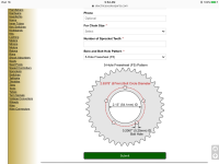
See
https://electricscooterparts.com/custom-made-sprockets.html

IMG_1302.PNG


The change in chain length needed when adding a deflector pulley at a position to just miss having the chain rubbing on the stay for this bike is miniscule.

The initial snug chain length was for connecting 30T driving 70T. How many chain links should be removed for connecting 24T to 56T to get the same snug fit? Knowing how to solve this will save you some trial & error chain fitting time. The math to calculate the number of links to remove is simple but the reason to do such is not so apparent.
 
How Sprocket Change Effects Chain Length Required.

On any 2-sprocket chain drive system the chain path has 2 straight sections of chain and two sections where the chain wraps around 1/2 the teeth of each sprocket. When a sprocket size is changed by N teeth, the chain sees only [N/2 X chain pitch] in necessary length change for a snug chain fit.

In my previous post sprockets were changed from 70T to 56T and 30T to 24T. The net chain length change is (70 - 56) /2 + (30 - 24)/2 = 10T. So 10 chain links removed would make for a snug fit.

It follows that a one tooth change on a sprocket necessitates a chain length change equal to the chain pitch/2, which for 40 series chain would be 0.5"/2 = 0.25 inches.

As for changes in actual chain length that can be made, multiples of 2 links must be added or subtracted from the existing chain length when there are no half-link sections available. Neither #410H chain or #415 chain have half links sections available. Adding or subtracting 2 links of 40 series chain will make for a one inch change in chain length.

The particular sprockets we choose for our "divine" gear ratio sometimes can make for a loose chain fit of almost 2 links. Add this almost 2 links of chain slack to what the suspension travel changes in chain length required are and we find that this seemingly necessary slack can make for a somewhat loose chain. Some of this slack can be removed at 1/4 inch per tooth increase on a sprocket. Never mind the exact gear ratio you wanted. Performance on an edirtbike is sick when there is more chain slack than the tensioner can take up -- giving incessant chain derailment.

The fitting process for a good chain fit is facilitated when we know how many links of chain we must allocate to get the suspension travel we want.

Next time I will elaborate on a surrogate measurement method for determining chain slack to allocate for suspension travel desired. The Specialized Big Hit bikes I use need about one link of chain slack to permit the normal range of swingarm travel.
 
Surrogate Measurement for Chain Length Change for Full(used) Range of Swingarm Travel

If we were making an actual measurement to determine maximun chain length change during swingarm travel we would measure the 2-sprocket system chain perimeter at all locations of the swingarm travel and then subtract from the maximum perimeter the minimun perimeter. This surrogate method watches the radius change of the swingarm radius of the rear tire axle about the BB axle.

IMG_1485.jpg

The first measurement is taken when the swingarm is held in place with the rear shock fully uncompressed.

IMG_1444.jpg


For the second measurement remove the rear shock as it gets in the way of full the full range of suspension motion if unbolted from just the swingarm and, if left fully in place, the swingarm is too hard to move thru the compression cycle. For this Specialized Big Hit frame the measured radius keeps getting larger as the swingarm goes into more compression. We are only interested in how much this radius changes during the swingarm motion permitted when the shock is in place and being compressed.

The amount of rear shock travel you maximally use is historically recorded in the distance from begining of the dust line on the shock rod to the shock cylinder top. If you have an "O" ring marker here, its location is even better for your use. For my rear shock this dust line is less than 2 inches from the shock top. With the shock out of the bike measure the pin-to-pin distance on the shock. For the Fox DHX 4.0 this distance is 8.5". For this setup the compressed shock distance pin hole to pin hole is 8.5" - 2" = 6.5". The position of the swingarm at your max compression will be when there is 6.5" between the Horst Bar shock hole and the shock hole on the frame. To hold your max compression position for measurement and chain fitting fix the swingarm in that place with a piece of wood such that the wood bolts in place of the shock with a span of 6.5"

IMG_1514.jpg

The Specialized Big Hit bike was designed for downhill Big Air flights (cushion big drops). I do not ride for Big Air so my bike's rear suspension never gets a full travel of 70mm with 650lb/in springs. To allow for 70 mm of travel would make for needing more chain slack which I likely would never consume for the suspension compressions I encounter..

IMG_1508.jpg

After the wood spacer is bolted into place measure the radius of the rear axle about the BB axle. For the Big Hit suspension this distance is 138/8". The change in radius distance is 138/8" - 136/8" = 2/8" = 0.25". This distance elongation will make the chain perimeter bigger by 2 x 0.25" since both sides of the chain run that connect the sprockets must increase by 1/4". The slant chain distance for a 30T to 70T sprockets system is about 1.0155 times longer than the rear axle to BB axle distance measurement. So that short extra distance of the chain slant is deemed insignificant for suspension travel chain length change. This suspension system therefore is said to consumes one link of chain slack when going from uncompressed to fully compressed to allow for full use suspension travel. Or a link of chain slack is necessary to prevent short chain suspension snubbing.

With the suspension held in place with the wood spacer chain fitting begins. More on this next post.
 
Chain Fitting

On this bike suspension frame the chain perimeter gets larger as the suspension goes into compression. For the frame I have choosen and allowed 2" of rear shock travel there will be an increase in chain length of one link beyond what length the sprockets need when in no compression. If we install the chain with the suspension fixed in compression with the wood spacer in place we will will not be snubbing the suspension travel we desired. But we sometimes with poor fitting can get more chain slack than our chain tensioner can take up adequately for bumps encountered in edirtbiking. Just under 3 links slack at no compression to too much slack for a simple tension idler to keep the chain on most of the time.

Worst case?

Chain fitting begins with the chain tensioner left out of the loop but any fixed deflection idler pulleys are kept in the fitting process. Suppose the chain is wrapped around sprockets of 60T, 26T and a fixed deflection pulley yielding a chain length of 0.05" too short for inserting the master link. The typical response is to add 2 links to get a fit but this total slack when in "no compression" is as mentioned too much for a good working of a simple chain tensioner. Instead of adding 2 links we could have reduced the total tooth count of our sprockets by one tooth and this change would have reduced the necessary chain circumferance by 1/4". By going to a 25T sprocket the slack at installation would become 0.25" - 0.05" = 0.20". The tension idler would get one link plus 0.2" = 0.5" + 0.2" = 0.70" slack at "no compression which it can easily handle.

By increasing or lowering the total chain ring teeth count at 1/4" per tooth change we can get a chain fit to within just under 1/4" slack at compression installation.


Measuring Chain Slack on a Ready to Ride Bike

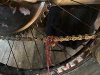
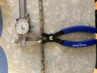
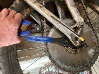
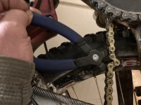
There are a couple methods to measure chain slack at "no compression" with the rear shock installed. The slack measuring process is done easiest with a Park Tool MLP-1.2 otherwise it can be done using some strong string as the "block and tackle" method. With the chain tensioner spring disconnected gather the extra links downward. See first 2 pics below for the gathering process.

IMG_1512.jpg

IMG_1513.jpg

IMG_1521.jpg

IMG_1532.jpg

For 410H chain shown and the gathering configuration where there are 2 links pulled out of the overall length the measured slack = 2 links - reading of caliper = 1.0" - 0.4" = 0.6" slack = 1.2 links = more than adequate slack for suspension and a slack chain length amount that the chain tensioner can handle adequately. The chain tension can handle adequately about a link and one half of slack = 1.5 x 0.5" = 0.75". If the slack exceeds 0.75" a stronger spring on the tensioner may help?

IMG_1535.jpg

IMG_1252.PNG

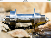
Essentially the ENO rear hub permits excellent chain fitting with any combination of sprocket teeth.
 
12 week preorder on this hub. And sadly only up to 135mm wide, so no fat bike. Interesting concept. It would allow single speed set ups on bikes with vertical drop outs and without a typical chain tensioner, so an aluminum bike or maybe carbon fiber if you wish. Most horizontal dropouts on anything but road/track/race bikes are diy which requires welding which is going to make it a steel bike, usually. We’ll see if this leads to more build options for higher power mid drives that are single speed. Cyclone 40A and 60A and lightning rods blocks and the QS motors 1000, 2000 and up can all do this.
 
Skaiwerd,

Re: ENOS hub

My QS 2000 bike has the ENOS hub. The 10,000 watt motor with <8:1 gearing under high power demand surges against difficult terrain and has rotated the offset blocks of this hub (pulling the axle towards the BB and thus making for additional chain slack leading to chain derailment). The axle is tightened to the frame with a 6mm Allen wrench headed bolts. I had been tightening these bolts with a T handle Allen wrench but now use a long handle Allen wrench to get these tighter than the T handle tool's short are permits.

The QS3000 powered bike would likely need these bolts even tighter.

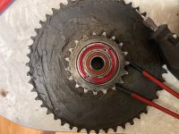
White Industries freewheel sprocket's lockring comes loose when the assembly is used as secondary chain driver sprocket.

The left hand thread on the lockring of RH White hubs when used as right hand chain feed to drive a wheel will self tighten due to its rotational inertia. When this sprocket freewheel is used in the DSBBH as a driver the torque enters through the threaded body part and exits on the driver sprocket teeth of the secondary chain system. When the assembly is used in this direction the lockring is subject to inertial loosening.

The ring is quite soft aluminum -- so easy on the tightening. I have tried red loctite thread lock but eventually discovered the ring loose. The ball bearings have a retaining ring and do not fall out if the ring is off. The ring is threaded into some HS alloy steel. I attempted adding Allen bolt holes at the thread interface but the spinning drill bit slid mostly into the aluminum. I coated the lockring threads and filled the 2 drill holes with JB quickest. Results later ...

IMG_1576.jpg
 
Stopping ENOS Hub Eccentric Rotation

The QS-3000 motor as geared on this edirtbike 42/19 x 42/16 = 5.80 [the bike can still do standing burnouts] can generate enough chain pull on the ENOS hub eccentric adjusting nut to move the nut angle towards the adjustment giving the most chain slack which makes for a loose chain and chain derailments. This slippage occurs even when the axle nuts are tightened very tight with a long arm Allen wrench. The fix I have done is to gear clamp a Park 19mm open-end slim wrench on the adjusting nut and clamp the wrench to the upper frame stay at the adjustment to yield 1 link of chain slack when the rear shock is not compressed.

08B16A29-6FC4-4ADB-903D-6B6956B8B39F.jpeg

Since the Specialized Big Hit rear suspension has anti-sag the chain gets tighter as the rear shock assembly goes into compression. So upon acceleration [with the primary/secondary gearing about the BB axle] the seat and frame rise, not sag. To make sure the rear suspension is not snubbed for full suspension movement by too short of chain length any ENOS eccentric axle change must be checked for sufficient slack to allow for full suspension. You can easily determine the amount of chain slack needed for full suspension with the rear shock disconnected.

5C3AEBEC-0FDE-4B70-ABFE-B7B43CEFB38C.jpeg
 
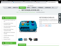
A Fardriver ND72530 FOC controller purchased giving 29,000 watts max to the QS3000 motor

630C5C16-4EB4-435D-B614-00F229B2E79B.png

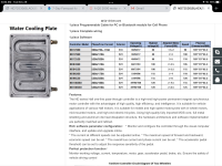
Fardriver makes a group of high output controllers: see the specs of one product line

79C79818-B2E3-4482-B6EC-F21EEB462FEF.png

For the whole of the product line up (box on the left) see: https://www.far-driver.com/nd72530black-blue/

88 volts x 330 amps = 29,000 watts

This chosen Fardriver controller’s output exceeds that of the 24F Next Gen PV controller. I did look into PowerVelocity.com controllers but got no response to email-questions about the 24F controller. When I hit the “add to cart” button the item was never placed in my cart despite their search showed the item in stock. So that lone controller is kind of water under the bridge as Fardriver offers five general controller model-categories that have within each group several controller output capacities. Specifically if you seek more speed you can chose higher voltage outputs — up to 130v and likewise if you want more torque (heat build-up?) you can find models with more amperage output while holding max voltage lower.

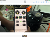
The sales person, Nicole of Newdoon Ebike is the seller I communicated with for the purchase of a QS motor and Fardriver controller. Her cell for text is +86 173 6530 5772. They are affiliated with eBay sales and not Alibaba.com . From the proof video they sent showing the motor and controller powered up are 3 screen shots from the video of the controller, QS3000 motor with reduction of 2.37 and a handheld remote dashboard (cell App?).

4947EF5A-0712-4F9B-ABBE-6D71E739F6D1.png

6B584783-598F-4F7A-B613-12CA10F89AF3.png

The build in reduction on the motor with driver sprocket 14T and rear wheel sprocket 34T will make for suitable single chain system having a gear ratio of 1:5.755 which means no DSBBH on the BB axle.

83472DFC-BA24-4096-9FE4-E99975E6DE09.png


The removed Votol EM 150 controller will be set-up on the QS 2000 motored edirt bike giving max wattage 84v x 150 amps = 13,200 watts. I suspect the motor can handle some 20,000 watts without its IPM magnets flying off.
 
Comparing controller Votol EM150 and the Fardriver ND 72530 (rated 330 amps line 530 amps phase @ 88v max). Labeling on the Fardriver is 350amp line.

The Fardriver controller replaced the Votol on the QS 3000 motored edirtbike. The bike is low geared as it can do a standing fixed against a wall burnouts [while I am sitting on the seat] just by throttling from zero. It’s gearing is 42/19 x 42/16 = 5.8.

I decided to simply top end test both controllers. The section of road use for the the test is slightly uphill giving two different top speeds for an out-run and back-run.

The Votol controller pushed the bike uphill at 51.4 mph and the downhill topping 57.7 mph.

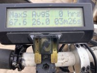
The Fardriver controller was tested as out of the box — no motor program mods had been done. The uphill run was 67.6 mph as measured by a calibrated CycleAnalyst(The CA was not hooked to the out power leads as max allowed amperage is 9999 watts). For the downhill run (just a slight downhill) I might break 70 mph? The downhill run blew a 120 amp fuse before getting beyond 67.6 mph— no new data— the higher phase amps getting a higher top end — more rpm max?

The best news: The motor was cold after these two runs. Likely the motor has plenty more safe heat capacity than the portion of the 120 amps x 80 volt = <10,000 watts dissipated as heat?

5102FA24-C093-426A-A27B-47098FC9CAB8.jpeg

The 1P21s LiPo 20 Ahr battery set has a 24C discharge rate = 480 amp. These batteries are sold with XT 90 terminals — likely the XT90’s would be smoke at 480 amps. The Votol test begun with full charge 87.5 v and the Fardriver was 80 v.
 
Back
Top