Hi
I just got my new Zero 10 electric scooter and in my country these scooters must be locked to a max speed of 20km/h
In the settings menu P8 (used to set max power) is locked to 39 and this value cant be changed.
(P8 needs to be locked for the scooter to be legal in my country so swapping it out with a new LCD display is not the best solution)
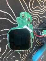
QS-S4 display:

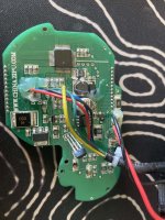
QS-S4 PCB:

The display is using the HR8P506 MCU and my first thought was to dump the firmware, modify it to unlock P8 only when the correct combination of some keypresses (using brake and mode button etc) so if I got pulled over I could just turn the display off and back on again and P8 would be locked. Problem is that this is some China MCU that I find less to no info about and coz of this I started with a different approach.
Does anyone know of a different type of LCD panel using a different MCU like a STM32, PIC controller or atmega etc?
For now I started to look at the communication between the LCD panel and the speed controller (ESC) and my goal is to modify this data and change max speed (P8) only after a USB dongle have been connected to the display's USB port to unlock this setting.
I will share my findings in case anyone else is interested in such.
---
On the PCB there are some wires coming from the ESC (6 in my case but other LCD panels is using 5) and two of these are marked TX and RX. This is UART using TTL levels set to 8N1 1200bps (serial known as RS232 on PC)
LCD panel is sending a chunk of 15 bytes to the ESC and will then read 15 bytes back from it.
LCD send:
01 03 01 00 05 05 1A 00 35 80 00 0A 1C 0A B0 <- First chunk after power on
01 03 02 00 05 06 1A 00 35 80 6C 0A 1C 0A DC
...
01 03 16 00 05 7A 1A 00 35 00 6C 0A 1C 0A 34
01 03 17 00 05 7F 1A 00 35 00 6C 0A 1C 0A 30
01 03 18 00 05 78 1A 00 35 00 6C 0A 1C 0A 38
00 03 19 00 05 7D 1A 00 35 00 6C 0A 1C 0A 3C <- Last chunk after I pressed power off
This is what I found out about these bytes:
B00 B01 B02 B03 B04 B05 B06 B07 B08 B09 B10 B11 B12 B13 B14
01 03 18 00 05 78 1A 00 35 00 6C 0A 1C 0A 38
B00 = Power on/off (01=on. 00=off)
B01 = 03 ?
B02 = Packet Counter. (Counts from 0 to 0xFF and then restarts. 1 packet is all 15 bytes)
B03 = 00 ?
B04 = Gear (Using bit 0, 1, 2, 3. xxxx0101=1, xxxx1010=2, xxxx1111=3)
B05 = ?? rand?
B06 = P09 = Kickstart (Only bit 1 is used. xxxxxx1x=kickstart, xxxxxx0x=no kick) (Usually 0x1A for kickstart)
B06 = P17 = Cruise Control (Only bit 2 is used. xxxxx0xx=off, xxxxx1xx=on) (Usually 0x1A for off)
B07 = 00 ?
B08 = P08 = Power Limit
B09 = Lights on/off (Using 1 bit 3. xxxx0xxx=off, xxxx1xxx=on)
B09 = Brakes on/off (Using 1 bit 6. x0xxxxxx=off, x1xxxxxx=on)
B10 = 0x6D or 0x6C ??
B11 = P11 = Electronic Breaking (Using bit 3, 4, 5. xx000xxx=0, xx001xxx=1, xx010xxx=2, xx011xxx=3, xx100xxx=4, xx101xxx=5) (Usually 0x1A for 3)
B11 = P12 = Acceleration (Using bit 0, 1, 2. xxxxx000=1, xxxxx001=2, xxxxx010=3, xxxxx011=4, xxxxx100=5) (Usually 0x1A for 3)
B12 = 0x1C
B13 = P06 = Wheel Diameter
B14 = XOR checksum (That is when all 15 bytes are xor'ed the sum should be 0x00)
This display comes from an Zero 8 and is locked to 0x35 (53) and I am pretty sure that this is byte 8 on this chuck.
So I will try to connect a small MCU to intercept this block, modify this B08 byte and send it to the ESC with and updated checksum at the end. I am planning on using an Atmel 32U4 (Arduino Pro Micro) which is a pretty small board and should fit inside the LCD panel. This MCU has native USB support and I will connect this port to the LCD panels USB port which is used only to charge your phone etc.
The response from the ESC is a bit more messy:
36 09 00 2B 2B 2B 00 2B 2B 2B 2B 36 E5 2B EC
36 0A 00 24 24 24 00 24 24 24 24 33 C6 24 C9
36 0B 00 29 29 29 00 29 29 29 29 38 CB 29 CE
36 0C 00 52 52 52 00 52 52 52 52 C7 83 52 7E
B00 always start with 0x36 (Or I have not seen this byte change)
B01 is a counter going from 0x00 to 0xFF and then restarts.
B02 ? (always 00)
B03, B04 and B05 are used to signal the LCD that the brake was pressed in a very strange way.
-These three bytes seems to be random but they are all the same unless you press the brake.
-If brake is pressed then 0x20 will be added to B04. (LCD panel will verify this by setting bit 6 in B09. See above)
B06 = (always 00)
B07, B08, B08 and B10 is only changed when the rear wheel is rolling so I believe this is to set your current speed on the LCD
-I have not figured how this is decoded yet coz these bytes is also changing all the time.
..
B14 XOR checksum
The receive chunk is not important for my mod to work so I might leave this connected to the HR8P506 MCU.
If anyone have some more info about these LCD panels then that would be great.
I just got my new Zero 10 electric scooter and in my country these scooters must be locked to a max speed of 20km/h
In the settings menu P8 (used to set max power) is locked to 39 and this value cant be changed.
(P8 needs to be locked for the scooter to be legal in my country so swapping it out with a new LCD display is not the best solution)
QS-S4 display:
QS-S4 PCB:
The display is using the HR8P506 MCU and my first thought was to dump the firmware, modify it to unlock P8 only when the correct combination of some keypresses (using brake and mode button etc) so if I got pulled over I could just turn the display off and back on again and P8 would be locked. Problem is that this is some China MCU that I find less to no info about and coz of this I started with a different approach.
Does anyone know of a different type of LCD panel using a different MCU like a STM32, PIC controller or atmega etc?
For now I started to look at the communication between the LCD panel and the speed controller (ESC) and my goal is to modify this data and change max speed (P8) only after a USB dongle have been connected to the display's USB port to unlock this setting.
I will share my findings in case anyone else is interested in such.
---
On the PCB there are some wires coming from the ESC (6 in my case but other LCD panels is using 5) and two of these are marked TX and RX. This is UART using TTL levels set to 8N1 1200bps (serial known as RS232 on PC)
LCD panel is sending a chunk of 15 bytes to the ESC and will then read 15 bytes back from it.
LCD send:
01 03 01 00 05 05 1A 00 35 80 00 0A 1C 0A B0 <- First chunk after power on
01 03 02 00 05 06 1A 00 35 80 6C 0A 1C 0A DC
...
01 03 16 00 05 7A 1A 00 35 00 6C 0A 1C 0A 34
01 03 17 00 05 7F 1A 00 35 00 6C 0A 1C 0A 30
01 03 18 00 05 78 1A 00 35 00 6C 0A 1C 0A 38
00 03 19 00 05 7D 1A 00 35 00 6C 0A 1C 0A 3C <- Last chunk after I pressed power off
This is what I found out about these bytes:
B00 B01 B02 B03 B04 B05 B06 B07 B08 B09 B10 B11 B12 B13 B14
01 03 18 00 05 78 1A 00 35 00 6C 0A 1C 0A 38
B00 = Power on/off (01=on. 00=off)
B01 = 03 ?
B02 = Packet Counter. (Counts from 0 to 0xFF and then restarts. 1 packet is all 15 bytes)
B03 = 00 ?
B04 = Gear (Using bit 0, 1, 2, 3. xxxx0101=1, xxxx1010=2, xxxx1111=3)
B05 = ?? rand?
B06 = P09 = Kickstart (Only bit 1 is used. xxxxxx1x=kickstart, xxxxxx0x=no kick) (Usually 0x1A for kickstart)
B06 = P17 = Cruise Control (Only bit 2 is used. xxxxx0xx=off, xxxxx1xx=on) (Usually 0x1A for off)
B07 = 00 ?
B08 = P08 = Power Limit
B09 = Lights on/off (Using 1 bit 3. xxxx0xxx=off, xxxx1xxx=on)
B09 = Brakes on/off (Using 1 bit 6. x0xxxxxx=off, x1xxxxxx=on)
B10 = 0x6D or 0x6C ??
B11 = P11 = Electronic Breaking (Using bit 3, 4, 5. xx000xxx=0, xx001xxx=1, xx010xxx=2, xx011xxx=3, xx100xxx=4, xx101xxx=5) (Usually 0x1A for 3)
B11 = P12 = Acceleration (Using bit 0, 1, 2. xxxxx000=1, xxxxx001=2, xxxxx010=3, xxxxx011=4, xxxxx100=5) (Usually 0x1A for 3)
B12 = 0x1C
B13 = P06 = Wheel Diameter
B14 = XOR checksum (That is when all 15 bytes are xor'ed the sum should be 0x00)
This display comes from an Zero 8 and is locked to 0x35 (53) and I am pretty sure that this is byte 8 on this chuck.
So I will try to connect a small MCU to intercept this block, modify this B08 byte and send it to the ESC with and updated checksum at the end. I am planning on using an Atmel 32U4 (Arduino Pro Micro) which is a pretty small board and should fit inside the LCD panel. This MCU has native USB support and I will connect this port to the LCD panels USB port which is used only to charge your phone etc.
The response from the ESC is a bit more messy:
36 09 00 2B 2B 2B 00 2B 2B 2B 2B 36 E5 2B EC
36 0A 00 24 24 24 00 24 24 24 24 33 C6 24 C9
36 0B 00 29 29 29 00 29 29 29 29 38 CB 29 CE
36 0C 00 52 52 52 00 52 52 52 52 C7 83 52 7E
B00 always start with 0x36 (Or I have not seen this byte change)
B01 is a counter going from 0x00 to 0xFF and then restarts.
B02 ? (always 00)
B03, B04 and B05 are used to signal the LCD that the brake was pressed in a very strange way.
-These three bytes seems to be random but they are all the same unless you press the brake.
-If brake is pressed then 0x20 will be added to B04. (LCD panel will verify this by setting bit 6 in B09. See above)
B06 = (always 00)
B07, B08, B08 and B10 is only changed when the rear wheel is rolling so I believe this is to set your current speed on the LCD
-I have not figured how this is decoded yet coz these bytes is also changing all the time.
..
B14 XOR checksum
The receive chunk is not important for my mod to work so I might leave this connected to the HR8P506 MCU.
If anyone have some more info about these LCD panels then that would be great.