Razor RX200 6KW Build

nemondemon

1 mW
Joined
Jun 5, 2024
Messages
10
Location
United Kingdom
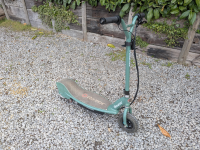
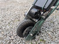
Just completed my latest build on an RX200 scooter. Tried to keep it looking as stock as possible (electric scooters are increasingly poorly received by the UK police) with an emphasis on power rather than range. Only geared for 44mph but climbs hills like a beast. Also the rigidly tensioned belt drive conversion means motor braking (and therefore regen) is now possible. Specification detailed below:

Drivetrain - Full Belt Drive Conversion​

Custom machined rear 72T timing pulley with freehub thread
Custom aluminium angle motor bracket
Eccentric rigid belt tensioner
14T motor pulley
5M belt (15mm width)

Motor​

Alien Power System 8072S 165KV 6000W

ESC​

Flipsky 75100 Pro V2.0

Battery​

3x 5S 7000mAh LiPo running in series (15S total)
ANT 110A BMS with passive balancing

Braking​

Conversion to Shimano MT200 hydraulic disc brake

EDIT: ESC failed within 2 rides; now upgraded to a Flipsky 75200 Pro V2.0
 

Attachments

  • 1746037926376.png
    1746037926376.png
    14.9 MB · Views: 15
  • PXL_20250423_172244099.jpg
    PXL_20250423_172244099.jpg
    4.2 MB · Views: 10
  • PXL_20250423_172249116.jpg
    PXL_20250423_172249116.jpg
    3.8 MB · Views: 12
  • PXL_20250423_172256729.jpg
    PXL_20250423_172256729.jpg
    3.8 MB · Views: 11
  • PXL_20250423_172315121.jpg
    PXL_20250423_172315121.jpg
    2.1 MB · Views: 13
  • PXL_20250423_172348973.jpg
    PXL_20250423_172348973.jpg
    2.7 MB · Views: 14
  • PXL_20250423_172357217.jpg
    PXL_20250423_172357217.jpg
    3.4 MB · Views: 14
Nice work. Looks like a very solid and reliable setup. I love how you say "only" geared for 44mph!

I have the same scooter and it feels unstable at 14mph.

Did you design/machine the pulley teeth yourself? I have been looking for some guidance lately on how to reverse engineer the tooth profiles of timing belts.
Thanks! I bought a standard aluminium HTD timing pulley (loads of places sell them online; usually bearing shops) then machined out the bore with a thread defined by the ISO 6696 standard (this dictates the thread size of ISO bottom brackets/freewheels for bicycles). This allowed me to screw the pulley straight onto the existing Razor wheel hub in place of the original freewheel & sprocket.

I would recommend going down this route of buying an off-the-shelf pulley and machining to suit. Whilst I've never looked through the HTD standard, I would imagine there are fairly tight geometric tolerances which will make machining a part from scratch quite expensive.

The modifications to my pulley were designed so that the part would only need to fixtured in the lathe once with just 2 machining operations (boring and thread cutting) to complete. This all helps in reducing machining cost.
 
Agreed, they are expensive to machine. Apparently the dimensions are closely guarded secrets that Gates and other belt companies will license to manufacturers but not individuals. HTD and GT profiles are readily available at reasonable prices so its smart to do it the way you did.

I have a project that would be great with some of the bicycle specific Gates pulleys like their CDX system. Problem is that I need tooth counts that don't exist. I figured anyone who has figured out the secret equations that determine these various belt profiles may be able to give me some tips.
That makes sense. I've 3D printed a few HTD pulleys in the past which have worked well but only in very low torque applications (not EV related projects). There are geometrical guides online which I guess will work to some degree but you'd still be in the dark on the exact sizes and tolerancing. I'd presume a higher tooth pulley (which I'm guessing is what you're looking for?) is going to be more sensitive to the geometry being perfect given many teeth will be in engagement
 
I'd presume a higher tooth pulley (which I'm guessing is what you're looking for?) is going to be more sensitive to the geometry being perfect given many teeth will be in engagement

Indeed. Apparently they build in a different amount of slop for different tooth counts. The pitch line is also outside of the pulley at a theoretical point in space. I wish it were as easy as a chain. With chain sprockets the chain always takes the shortest path between the 2 roller centerlines so no matter how bad you get the ends of the teeth its still just a bunch of circles at a known distance from each other. With CDX belts costing $120 each I really don't want to get the geometry wrong.

Anyway, cool scooter!
 
Back
Top