Razor upgrades? Nothing crazy.

Nope, beside drilling three holes and making a bracket for the controller and charger, the only real work to my conversion is building the battery. The rest is just bolting things up and cosmetics. It costs about $180 less and has 80% more power too.

On another note, my CHL (China Hobby Line) lipos came in today. I got two 3s 65C 5,000 mAh packs for the spot welder and one 6s 100C 1,500 mAh pack to run my new thermostatic, portable soldering iron. It should be able to run my soldering iron at full power for 30 minutes. With the iron's power saving features and normal use, I'm expecting it to go 2+ hours on a charge which is longer than any soldering job I have had to do and if I need more I can plug it straight in to the 24V PSU i got for the lipo charger and go 100% duty cycle until it melts.

A secondary use for my 5,000 mAh 3s packs is to run the portable hot glue gun. I dont use hot glue often but maybe I'll use it more if I'm not tethered to an AC outlet. If I parallel my 5,000 mAh packs it should run for quite a while, I just have to swap connectors because the XT60 version wasn't in stock.

I'm still waiting on my cell spacers. I haven't gotten tracking info yet. I really wish i had been able to find a US seller for those.

I'm stalled until i get those spacers and ultimately I'll be waiting on heat shrink too but I'll be able to assemble and bench test the battery, motor and electronics before then. For now, I have everything planned and I'm doing the mechanical work a little at a time because it will be done well before the battery.

Three more details of the cosmetics are settled I think. They are a suprise.
 
I got some of my stuff set up.

My power supply for the lipo charger and soldering iron came with a power cord and an XT60 cord but neither had spades for the terminal strip. The XT60 cord wires were thick enough for a good crimp on my insulated spades. The power cord was too thin, my crimps kind of held the wire in but there was some movement so I put my charger on my S6 lipo and it said it has about 57% charge so I plugged it in to my soldering iron and soldered my spades.

One thing I didn't think about is that my 3S lipos have XT90 connectors but my charger is XT60 and the parallel connector I got for spot welding was XT60 so no good for my purpose. To allow for charging and a parallel connection for spot welding, I got two Male XT90s, one female XT90, a female XT60 and about 8" of red and black wire. I stripped a lot of insulation off of one side of the two wires and threaded it between the XT90 parallel connections and I soldered all of that together, then I put some heat shrink on the wires and soldered them on the XT60 connector.

That adapter allows me to plug in one battery and connect to the charger with the XT60 or connect two batteries and plug it in to the spot welder (with no connection on the XT60).

That solder job I did with the iron plugged straight in to the power supply. It worked fine and after that I charged my 6s lipo and that worked fine too.

The adapter needs some cleanup. I might re-do it because there might be a stray wire or two shorting the terminals. It's not a problem with the soldering, I should have just tinned the ends of the wires to control them better.

Any way, once I am able to charge my 3s lipos and parallel connect them to my spot welder, I'll be ready to weld when the spacers get here.
 
I got my 13 tooth sprocket, heavy duty #25 chain (a bit of a misnomer but better than standard), new chain tensioner, new tires, new wheel bearings and new headset. That's all the hardware to complete the drivetrain mechanicals and maintenance parts (beside rear brake). I also got a three wire throttle connector kit.

I want to use a thumb throttle instead of a twist throttle so I ordered one but while it has crimped on connector terminals that look like a match to the existing throttle, it did not come with a connector housing. I'm going to use the connector kit instead of try to take the throttle housing off of the twist throttle.

I also received my Meanwell power supply which together with my BMS will create a balance charging system.

I couldn't do too much today but I got my new sprocket on the motor shaft. I might try changing the wheel bearings tomorrow. I want to try to install the new tires tubeless with sealant so no pinch flats and otherwise flat resistant. The tires are 3" rather than 2.5 or 2.75, a little more air spring volume and with an on-road style tread.

I might do the tensioner sooner rather than later but I'm saving the headset to see if I want to upgrade the fork. If yes, I'll have a new headset ready for it. If no, I'll have new bearings if the headset feels too gritty.

I finally got real tracking info for my battery spacers. They should arrive Monday. I'm going to try to be ready to glue in my cells and start spot welding Monday night. My crimper and balance lead JST-XH connectors should arrive Monday also.

After that, my hold up is heat shrink.
 
The crimper and connectors arrived early. I'll be testing them tonight or tomorrow. I want to make sure they make a good crimp.

I unrolled the fiber gasket insulator a few days ago. It had picked up a substantial curl from being rolled. I was able to reverse a lot of it by wrapping it around a door but the last 5-6" on each side still had the curl. Last night I stuck one end in a wire laundry rack to let the weight of the sheet pull the curvature to the reverse. In the morning it was quite improved so I switched ends. I just switched again and I think the sheet will be relatively flat by the morning. I could probably make it more flat by stacking heavy stuff on top of it on a flat surface but it will be fairly easy to work with as-is.

One thing I might try is silicone thermal interface material (TIM). It is something you would see on a cheap CPU heatsinks or factory applied heat sinks for RAM chips and chipsets. It is squishy and transfers heat better than a straight insulator so I was thinking I could wrap the perimeter of my pack with that and maybe wrap thin aluminum or copper sheet around that to make a metal shield that's also a heat sink. I ordered it late but if it is on track to get here before I'm ready to heat shrink the pack, I'll try it.
 
I finally put together my Malectrics spot welder. I used my new JST-XH crimper to put terminals on to my foot switch cable instead of the soldering they suggest. It worked and is clean. Once I confirm that the two wires i used are correct, I'll cut the third terminal off and heat shrink it.

Any way, i plugged in a battery and the foot pedal cord and it fired up and went to the normal screen at the default 5us setting, not the error from using the NC wires of the foot switch. It seems like it is ready to go once I fully charge my 3s lipos.

I have three flavors of nickel strip, some plain, some 2p and some 4p. I think I have some dead 18650s to practice on.

I kind of think Malectrics should redesign the case to make it one piece instead of a separate fuse holder part. A separate compartment for the fuse would be fine but I think it's going to be sliding around on my desk while I'm trying to spot weld. It's just a little unruly. It really should be a lot heavier to stay in place while I'm manipulating the spot welder electrode cables.

I'm going to do a little more tear down on my scooter while I'm still waiting on those spacers. I'll take off the rest of the body work, the old chain and the tensioner. Without bodywork, I'll be able to look at the current electric routing so that I can plan my new harness. I think I'm going to bench test the whole drivetrain with my battery and BMS to see if its bluetooth app is a good enough dashboard for me. If not, I'll route wires for a more generic ebike display. I should also plan wiring for my lighting. That could be headlight, tail light, brake light, hazards, underglow and 2-3 EL inverters so a bit complex. I don't think I'll make any type of turn signal lights, I don't want to add a switch for that so I'll use hand signals.

I think I might add a vehicle locator so I can find my scooter if it gets stolen.
 
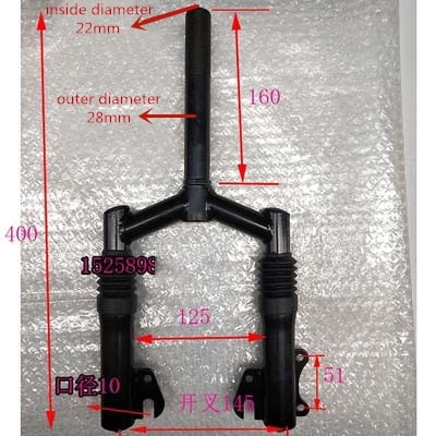
I found what could be the fork for you. Looks more solid than the stock, has a shock and takes a disc brake. I don't know if al the frames are the same but mine need a long neck, you can figure out if this will fit yours.

https://www.aliexpress.com/item/32983474524.html

HTB1Y6ypKMHqK1RjSZFkq6x.WFXab.jpg
 
That does look interesting. They don't list rake and I'm not sure if it is threaded or thread less. I see combos that have the fork, a motorized wheel, a disk brake and a fender but I can't seem to find the fender separate. I would need to do a wheel upgrade too.

I got my spacers!

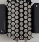
Here is my intended layout:
IMG_20200519_175632~2.jpg

It's about as wide as the old battery, a couple inches longer but about an inch shorter, just about identical volume, perhaps a bit lighter but after the nickel, insulation, BMS, heat shrink and wires, probably about the same.
 
Well, I've heard too much disagreement on what the rake really is, according to some you don't know the rake until you have it on the frame. it looks like the offset is about an inch. I haven't bothered to look at one of mine to see the stock offset or rake.
 
With a higher achievable top speed, more stability would be desirable so rake greater than stock would be ideal.

I got my cell spacers trimmed so tomorrow I will begin hot gluing the cells and getting my nickel ready to weld. The hot glue will be minimal, just to keep the shape while I build it up. The nickel will be more complicated. My 4p groups are not straight rows so my nickel resistance will be a bit higher than ideal which is why I will be folding and doubling it strategically. I may solder some copper to the nickel to strap the series connections. I would have made a more ideal cell layout but I am limited by the available width in the battery box.

In the above picture you can see one spot on the top and one on the bottom which I will fill with a piece of aluminum half round. This will eliminate the gaps on the perimeter of the pack so the whole thing will be tightly locked up when I shrink wrap it. The cell spacing is 22mm so the pack unwrapped is 131mm wide, 191mm tall and 70mm thick (without BMS).

Nickel plus insulation on the top and bottom should add about 3mm to height, if I add copper, that's more height. The BMS is about 28mm tall so my total should be about 102mm. The lead acid batteries are about 94.5mm tall not counting the top terminals so the height will essentially be equal. I will probably put a pad under the battery for extra insulation and to eliminate pressure on a potential rub spot so in reality, the top of the BMS will be a little taller than the top of the lead acid batteries.

One thing I have to think about is routing my BMS balance leads. The top should not be hard but 6 wires from the bottom have to come up. I would like to try to follow the can connection of its group of cells so a short from the balance lead to the nearest can will not flow any current.

Hopefully I will get a lot done tomorrow.
 
I was thinking about it and decided to test my 21700s.

They fit in my Opus BT-C3100 so I thought I could sort them and arrange them for the best thermal performance.

What I didn't think about when I started is with the default 500mA charge and discharge current, the test cycle takes about 25-30 hours. I was tired when I put them on and haven't used the charger in a while so I forgot how to bump it up to 1,000mA current.

Any way, the charge and discharge is taking a long time so I ordered a second charger. After I change the current setting, that should let me do 8 batteries in about 12-15 hours so a much increased rate but still kind of slow.

With my cubic stacking, the middle of the pack is going to be running warm so I'm going to group my worst internal resistance cells on the perimeter and the best in the center. I'm also going to make some effort to balance cell quality with the nickel resistance. I even have a plan for adding some silicone thermal interface material to promote heat flow and equalize the cell temperatures inside the pack.

I think I have figured out the best locations for my balance wire routing from the bottom of the pack.

My big heat shrink might even be arriving soon.

One other thing I might need is a big high current soldering iron.

I was able to solder 16 gauge wire in to some XT90s (charging leads, not high current) and was near the limit of my 60 watt thermostatic iron. When I start using 10-12 gauge, I'm expecting a bad struggle unless I get a more powerful iron.
 
So far, my cells seem to be testing out at around 4,800mAh according to my Opus charger and the 1A charge rate seems to give similar results to 500mA charge rate.

This tells me that 0.1C and 0.2C rates are nothing for these 21700 cells. A power calculator says I should be able to cruise at 13mph at 0.2C, 15mph at 0.3C and 18mph at 0.4C and some of the discharge curve tests suggest that the batteries perform pretty well up to about 2C discharge but that's probably in a more ideal thermal situation. The calculator also says 23mph is about 0.7C which is probably about as hard as I would want to push it for any substantial distance. Pushing harder would get a bit more speed but not be great for the battery for a sustained period. Of course accelerating from a stop or climbing up an overpass will increase the discharge rate momentarily but hopefully not long enough to heat the battery pack too much.

Theoretically that means a 65 mile range at 0.2C, 50 mile range at 0.3C, 45 mile range at 0.4C and about a 34 mile range at 0.7C.

Ideally I will try to keep my trip distance under 10 miles one way and charge at the midpoint so I'm only using about 30% of my range on a trip.
 
A little more calculation, it looks like 1,100 watts is required to attain maximum speed at 27.3mph and with an 1,800 watt motor, I should be able to maintain that riding in to a 10mph head wind or up a 4% grade.

A 7% grade drops the speed to about 21mph, not terrible.

I probably should have done that math before ordering my sprocket but 13 tooth still looks like a good choice. If I find that grades give me problems, I may go to a 12 tooth sprocket but it is pretty flat around here.

The Pocket Mod is a sit down scooter and the calculator I used does not specify if it uses wind resistance for a stand up or sit down scooter but it does mention that stand up scooters have higher wind resistance so my speed and efficiency on flat ground might be greater.

I'm having some trouble finding grade numbers of things like overpasses and the Sunnol Grade which actually has "Grade" in the name. It seems like mountain roads are limited to 7% maximum continuous grade but there are lots of exceptions for short streets and old routes.

Most of my climbing is going to be overpasses and maybe pedestrian bridges so it would be nice to know what grade they design with but that is knowledge that is probably only contained in some esoteric civil engineering text book. Google and Wikipedia have failed me.

The calculator does say I should be able to climb a 15% grade at 15mph so it seems unlikely that a grade would stop me but that would have the motor speed around 2,600 rpm, lower gearing for lots of climbing might be a good idea but as I said, it's pretty flat around here.

I found one, in a 43mb Caltrans road guide, it says pedestrian overpasses should have a maximum of 5% grade and another pdf had the design speed of 30' radius bicycle ramps at 12mph. The calculator says 12mph and 5% grade is 600 watts so 0.3C, easy. Motor speed should be 2,000 rpm, probably not an issue with that power.

The proof is going to be taking it on the road but I think my gearing will be good and my battery pack should be sufficient for the power required and deliver good range.
 
This post has been amazing! :bigthumb: :bigthumb:

I just picked up a Kiki pocket mod and want to be able to ride it to my work that's 15mi away.

Did youe mods work to expectation?
 
A little more calculation, it looks like 1,100 watts is required to attain maximum speed at 27.3mph and with an 1,800 watt motor, I should be able to maintain that riding in to a 10mph head wind or up a 4% grade.

A 7% grade drops the speed to about 21mph, not terrible.

I probably should have done that math before ordering my sprocket but 13 tooth still looks like a good choice. If I find that grades give me problems, I may go to a 12 tooth sprocket but it is pretty flat around here.

The Pocket Mod is a sit down scooter and the calculator I used does not specify if it uses wind resistance for a stand up or sit down scooter but it does mention that stand up scooters have higher wind resistance so my speed and efficiency on flat ground might be greater.

I'm having some trouble finding grade numbers of things like overpasses and the Sunnol Grade which actually has "Grade" in the name. It seems like mountain roads are limited to 7% maximum continuous grade but there are lots of exceptions for short streets and old routes.

Most of my climbing is going to be overpasses and maybe pedestrian bridges so it would be nice to know what grade they design with but that is knowledge that is probably only contained in some esoteric civil engineering text book. Google and Wikipedia have failed me.

The calculator does say I should be able to climb a 15% grade at 15mph so it seems unlikely that a grade would stop me but that would have the motor speed around 2,600 rpm, lower gearing for lots of climbing might be a good idea but as I said, it's pretty flat around here.

I found one, in a 43mb Caltrans road guide, it says pedestrian overpasses should have a maximum of 5% grade and another pdf had the design speed of 30' radius bicycle ramps at 12mph. The calculator says 12mph and 5% grade is 600 watts so 0.3C, easy. Motor speed should be 2,000 rpm, probably not an issue with that power.

The proof is going to be taking it on the road but I think my gearing will be good and my battery pack should be sufficient for the power required and deliver good range.
Did you ever finish this project? Did you end up doing a fork upgrade?
 
Back
Top