• Hello ES! We could use some help to get us past the finish line on building the new knowledgebase for the forum.
    Can you donate? Please see our fundraising page. Thank you!

Rectifier Emerson R48-3500e/3200e MOD - Voltage Adjust - 13.65v to 53.9v

jairbj

🔌 New-ish
Joined
Sep 2, 2019
Messages
16
Hi friends, finally I managed to mod my Emerson R48-3500e to make it voltage adjustable. It may work on 3200e as it is the same board.

It can be adjusted down to 13.65v and I achieved a maximum of 59v (didn't test more than this).

Below 13.6v it shuts down itself (maybe low voltage protection), so you have to turn it off and on again.

This is not the final version of this tutorial as I'm still trying resistor values.

To sum up you have to modify R621 and R625 from the small board.

I put a potentiometer on both to play with the adjustable range. At this moment I could get a variable voltage of 13.65 to 53.9v (I could achieve higher than that by for safety I decided to stay within this limit).

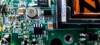
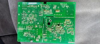
Here are the pictures of the board:
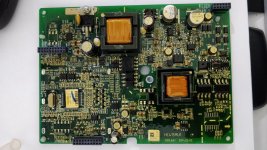
IMG_20210603_212546.jpg

Here is the location of the resistors:
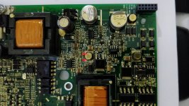
IMG_20210603_212615 - Copy.jpg

On my board both resistors are 21.5k and my board is factory adjusted to 53.2v.

What I tried first was to play only with R621 with these results:
Resistance -> Output Voltage
21.5k -> 53.2v
0 -> 29.8v

As soon as I try more value I'll post the results.
 
Today I measured the resistance I am using with potentiometers instead of fixed resistors and I have these values:

R621 = 9.28k
R625 = 0-34.14k pot.
This gives me voltage from 13.65v to 53.9v.
If I increase the max resistance of R625 I can achieve higher voltage.

*All values measured with a Fluke 17b+ multimeter.
 
Yesterday I finished testing the configuration I'm going to use.

R621 = 9.1k 5% resistor (measured 9.26k).
R625 = 100k pot (measured 103k) in parallel with a 51k 5% resistor (measured 52.2k)
It gives a resistance on R625 between 0 and ~ 34.65k.

This setup gave me an adjustable voltage between about 13.6v and 54.8v

During my tests within this setup, the R621 should be 9.28k or higher, otherwise, it can trigger the low voltage shutdown when R625 is set at minimum resistance (0). With 9.26k sometimes it gets voltage as low as ~13.54v and sometimes it triggers low voltage protection. With a 9.28k (got this value with a pot) it gets ~13.65v and it never disarmed during my tests.

*All values measured with a Fluke 17b+ multimeter.

As soon as I finish modding it I'll post pictures of this setup.
 
Hi Buddy

Thanks a lot for your clarification, but a picture tell more thank worlds ;)

Can you show us your final results?
I’m very interested in for my 48V goal

King regards

Éder
 
ederwillian said:
Hi Buddy

Thanks a lot for your clarification, but a picture tell more thank worlds ;)

Can you show us your final results?
I’m very interested in for my 48V goal

King regards

Éder

Hi friend, I didn't finish my project yet, so I don't have many pictures for posting.

If you just want 48v you have two options:
1 - Replace just the R625 resistor (default 21.5k) with a lower resistance one.
2 - Program your power supply with a programmer. I have a programmer in hand but didn't have time for debugging the protocol and create my version of this one.

For option 1 you can remove R625, solder 2 wires (as I deed), and hook different resistors, like 22k, 20k, 18k...
Then measure the output and choose the best resistor for you.
Alternatively, you can hook a 22k potentiometer and you'll have an adjustable output of ~26v to ~50v.

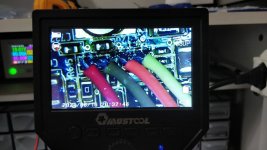
Wires soldered
IMG-20210616-WA0016.jpg

Fitting test of the 3d printed front with accessories
IMG_20210708_222654.jpg
 
What a great news ,

I’m going with your first option replacing R625 with a 22k potentiometer .

We share the same country I’m in São Paulo state / Ribeirão Preto

I’m using for psu for induction heater project .

Really thanks a lot
 
ederwillian said:
What a great news ,

I’m going with your first option replacing R625 with a 22k potentiometer .

We share the same country I’m in São Paulo state / Ribeirão Preto

I’m using for psu for induction heater project .

Really thanks a lot

Hi friend, I live in Brasilia/DF.

I wish you good luck with your project.

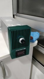
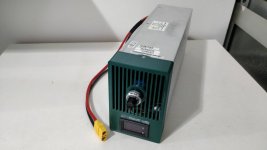
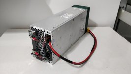
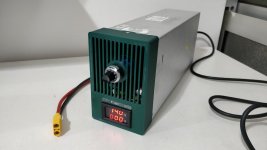
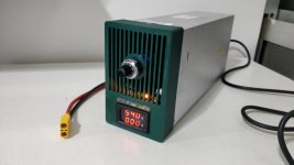
I think I finished the mine. At least for now.
 
Project finished (at least for now).

Adjustable from 14v to 54v.

Still want to put a current control on it.

WhatsApp Image 2021-08-26 at 10.26.06 PM.jpeg
WhatsApp Image 2021-08-26 at 10.26.08 PM.jpeg
WhatsApp Image 2021-08-26 at 10.30.34 PM.jpeg
WhatsApp Image 2021-08-26 at 10.30.34 PM (1).jpeg
 
jairbj said:
Yesterday I finished testing the configuration I'm going to use.

R621 = 9.1k 5% resistor (measured 9.26k).
R625 = 100k pot (measured 103k) in parallel with a 51k 5% resistor (measured 52.2k)
It gives a resistance on R625 between 0 and ~ 34.65k.

This setup gave me an adjustable voltage between about 13.6v and 54.8v

During my tests within this setup, the R621 should be 9.28k or higher, otherwise, it can trigger the low voltage shutdown when R625 is set at minimum resistance (0). With 9.26k sometimes it gets voltage as low as ~13.54v and sometimes it triggers low voltage protection. With a 9.28k (got this value with a pot) it gets ~13.65v and it never disarmed during my tests.

*All values measured with a Fluke 17b+ multimeter.

As soon as I finish modding it I'll post pictures of this setup.

Hi, it is great proect.
I have same project to adjust the voltage for Emerson rectifier but different model such as R48-2000E.
Would you suggest me how identify which resistor should be replaced.
I have no idea to identify which comparitor IC or deviding resistor which used to control the voltage.
Thanks in advance.
 
nuril said:
Hi, it is great proect.
I have same project to adjust the voltage for Emerson rectifier but different model such as R48-2000E.
Would you suggest me how identify which resistor should be replaced.
I have no idea to identify which comparitor IC or deviding resistor which used to control the voltage.
Thanks in advance.

Hi friend, unfortunately, I'm not a specialist in electronics to the level of identifying the comparator IC.

What I did was searching on the internet (more than a month searching) until I finally found about these two resistors in a Korean Blog using google translator (https://m.blog.daum.net/soft_wind/5867134). After that, I used my basic electronics knowledge to calculate the resistors and tested them.
 
jairbj said:
Hi friend, unfortunately, I'm not a specialist in electronics to the level of identifying the comparator IC.

What I did was searching on the internet (more than a month searching) until I finally found about these two resistors in a Korean Blog using google translator (https://m.blog.daum.net/soft_wind/5867134). After that, I used my basic electronics knowledge to calculate the resistors and tested them.

It is lucky you finding such that's article
I am still searching all information related modding Emerson R48-2000e but so far not lucky yet.
Anyway thanks for your feedback.
 
Project finished (at least for now).

Adjustable from 14v to 54v.

Still want to put a current control on it.

View attachment 301473
View attachment 301470
View attachment 301472
View attachment 301471
Olá Jair, tudo certo? Cara fiz uma modificação parecida com essa tua, tirando um resistor e colocando o potenciômetro de 100k, obtive de 28,7 a 58V, mas quero fazer como tu fez, mas gostaria de obter mais detalhes, como por exemplo como fez o esquema de ligação do mostrador de tensão e corrente. Outro detalhe, tu tirou a ventoinha da parte da frente? Desculpa o monte de perguntas, mas e que estou a muito tempo buscando informações e consegui agora com a tua postagem. Fico no aguardo! Abraço!
 
I know this is an old post but I'm stuck! I have an Emerson R48-3500e but the board is different from the one shown on here. The R625 resistor is not as indicated. Do I try and locate R625 elsewhere or is it a different resistor o need to find? IMG_20240421_180129.jpg
 
Answered my own question, so thought I'd add an update for potential future enquiries. I found R625 on the opposite side of the board. I removed this resistor and instead connected a 22k ohm potentiometer. I then powered up the board and found that the potentiometer was able to vary the output voltage as expected.
 

Attachments

  • IMG_20240421_194738.jpg
    IMG_20240421_194738.jpg
    4.3 MB · Views: 54
Good evening everyone, I followed with great interest the guide of jairbj but I did not understand where he found the instrument that measures voltage and current and where it should be connected, because I bought one on aliexpress but the voltage despite setting it to 13.85V makes me see dancing 9v 10v 15v 7v and so on...
 
the usual reason for "dancing voltage" is that the source is not a steady output, but is pulsing on and off, and the capacitors on it's output stage are smoothing this a bit so you don't just see full on and full off.

that can be from an overload condition causing it to crowbar itself off in protection mode, then back on to see if the overload is gone, etc., or it can be from a failure inside the psu, or a failure inside the voltmeter causing a short once voltage reaches a certain level.
 
the usual reason for "dancing voltage" is that the source is not a steady output, but is pulsing on and off, and the capacitors on it's output stage are smoothing this a bit so you don't just see full on and full off.

that can be from an overload condition causing it to crowbar itself off in protection mode, then back on to see if the overload is gone, etc., or it can be from a failure inside the psu, or a failure inside the voltmeter causing a short once voltage reaches a certain level.
not really, because I put a laboratory multimeter setting the power supply to 13.8V and it is perfectly still without jokes, but with the instrument that I should connect that measures voltage and current I see these measurements dancing, I would like to understand where the author took the voltage to power this instrument and in what way

 
Ah. That sounds like a problem with the meter itself--manufacturing mistake most likely, but counterfeit parts used inside it are another possibility.

Most of the meters like that I have seen have a separate power supply to operate them from what they are measuring. If you operate them off the same supply, then depending on the meter design they may not operate as expected (because of internal voltage references).

For those that can't operate from the same supply they're measuring, some people have used a separate battery to operate them on their EV, and others have used a DC-DC running off the traction battery of their EV.
 
Ah. That sounds like a problem with the meter itself--manufacturing mistake most likely, but counterfeit parts used inside it are another possibility.

Most of the meters like that I have seen have a separate power supply to operate them from what they are measuring. If you operate them off the same supply, then depending on the meter design they may not operate as expected (because of internal voltage references).

For those that can't operate from the same supply they're measuring, some people have used a separate battery to operate them on their EV, and others have used a DC-DC running off the traction battery of their EV.
No, it is not a question of manufacturing defects or anything else, after a careful investigation to power the voltage and current reading instrument it was taken directly from the fan, even if the voltage can be variable from 6-12V the instrument works but the third yellow wire which is responsible for reading the voltage and was put in the positive output 13.8V-54V but be careful the negative of the fan is not in common with the negative output 13.8V-54V so I wanted to know where you took the right negative to power the voltage and current reading instrument, thank you in advance.
 
Привет, это отличный проект.
У меня есть аналогичный проект по регулировке напряжения для выпрямителя Emerson, но другой модели, а именно R48-2000E.
Подскажите, пожалуйста, как определить, какой резистор следует заменить.
Я понятия не имею, какой именно компаратор или делительный резистор использовался для регулирования напряжения.
Заранее спасибо.
Здравствуйте! Я тоже купил блок питания Emerson R48-2000E. Вы нашли какие-нибудь способы его модификации?
 
Hi, it is great proect.
I have same project to adjust the voltage for Emerson rectifier but different model such as R48-2000E.
Would you suggest me how identify which resistor should be replaced.
I have no idea to identify which comparitor IC or deviding resistor which used to control the voltage.
Thanks in advance.
Hello! I also purchased an Emerson R48-2000E power supply. Have you found any methods for modifying your Emerson R48-2000E?
 
Good afternoon, but hasn't there been any further discussion about modifying this power supply?
I'm also curious if it's possible to limit the current and install short-circuit protection. Being a large power supply, it can be dangerous to handle, so it would be nice to take all the necessary precautions. If anyone is working on it, please let me know.
 
Back
Top