Kingfish
100 MW
Greetings
When adapting battery sources exceeding 72V, a few gifted members of this forum have used the TL783 to usurp the role of the LM317 voltage regulator (the common 12V supply for Infineon/116 controllers within the 36-48V realm). There are a couple good threads on the implementation:
Infineon transistor modification
116 Controller 6 FET Input Regulator Mod
Infineon Controller Technical
And yet for a non-EE type I find directions to be a bit too cryptic. Though once my knowledge of calculus was enough to operate nuclear reactors, today in the world of software I have retained just enough to attenuate audio from a Slider Common Control; it is I fear enough to apply Ohm’s Law. Still, it does not make me a qualified circuit designer; when wading into these waters I would be hard pressed to know the difference between carp nibbling at my toes over piraña.
Though truly an optimist, I am skeptical of swapping out the LM317 with the TL783 and expecting it to work. I am sure others would like to employ this device with the same spirit and enthusiasm, therefore I wish to demystify the process for the less-talented denizens.
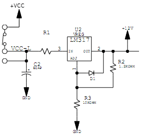
With many Infineon controller schematics the 12V regulator circuit looks very much like this.

In previous threads R1 had to be adjusted depending on the source voltage. We seek to eliminate this requirement, and apply an any voltage mod.
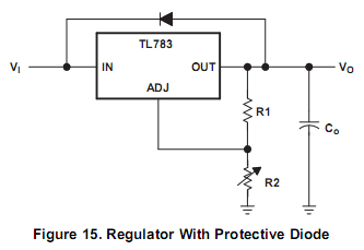
The TL783 specification (found here) suggests in Figure 15 that we use R2 to set the output voltage and R1 to set the output Current.

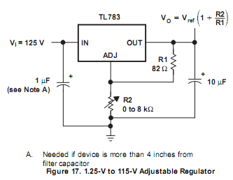
Figure 17 is a bit tidier but lacks the diode protection.

I actually like the diode concept though I don’t know what a reasonable value could be. Warning: Noobnessness chops showing
Math:
Between the two regulator devices we can see that the implementation is not precisely a 1:1 match; some slight adjustments shall be required. I have developed a spreadsheet that calculates various output voltages with corresponding R2 values. (Wouldn’t it be fun to have a little embedded Jscript app that does this for us on ES?) Note that in the calcs below the output current is set to 15mA by R1 (please correct me if I am wrong).
Based on what I have read the second set of equations presumes that we will need 60mA to drive the controller properly.
Just for curiosity, if we didn’t change R2 and R3 on the Infineon/116 board, our results would be:
Heat:
I am a little concerned with excess heat. One gent suggested that we place a resistor across Vin and Vout to shed some of the load. I see on the controller schematic that something like this was employed on the 5V supply – but it appears to be more about current limiting rather than assuaging heat. Truly, 5W of heat doesn’t bother me much in the Pacific Northwest especially if I could pipe it to my seat in the winter, although if I were crazy enough to charge WOT mid-day across Black Rock Desert playa on the way to Burning Man, um ~ yes the point is well taken.
This is where the piraña swim in closer than my toes
As Ringo said ~ I could use “A little help from my Friendsâ€Â
Thanks, KF
EDIT: update current from 0.060 to 0.065; added another link.
When adapting battery sources exceeding 72V, a few gifted members of this forum have used the TL783 to usurp the role of the LM317 voltage regulator (the common 12V supply for Infineon/116 controllers within the 36-48V realm). There are a couple good threads on the implementation:
Infineon transistor modification
116 Controller 6 FET Input Regulator Mod
Infineon Controller Technical
And yet for a non-EE type I find directions to be a bit too cryptic. Though once my knowledge of calculus was enough to operate nuclear reactors, today in the world of software I have retained just enough to attenuate audio from a Slider Common Control; it is I fear enough to apply Ohm’s Law. Still, it does not make me a qualified circuit designer; when wading into these waters I would be hard pressed to know the difference between carp nibbling at my toes over piraña.
Though truly an optimist, I am skeptical of swapping out the LM317 with the TL783 and expecting it to work. I am sure others would like to employ this device with the same spirit and enthusiasm, therefore I wish to demystify the process for the less-talented denizens.
With many Infineon controller schematics the 12V regulator circuit looks very much like this.

In previous threads R1 had to be adjusted depending on the source voltage. We seek to eliminate this requirement, and apply an any voltage mod.
The TL783 specification (found here) suggests in Figure 15 that we use R2 to set the output voltage and R1 to set the output Current.

Figure 17 is a bit tidier but lacks the diode protection.

I actually like the diode concept though I don’t know what a reasonable value could be. Warning: Noobnessness chops showing
Math:
Between the two regulator devices we can see that the implementation is not precisely a 1:1 match; some slight adjustments shall be required. I have developed a spreadsheet that calculates various output voltages with corresponding R2 values. (Wouldn’t it be fun to have a little embedded Jscript app that does this for us on ES?) Note that in the calcs below the output current is set to 15mA by R1 (please correct me if I am wrong).
Code:
Vout = Vref(1 + R2/R1)			Vref = 1.25		R1 = 82
therefore	 (test case)		I = V/R therefore I = 1.25/82 = 0.015A
R2		Vout
8000	123.2012195
3300	51.55487805
----------------------------------------------------------------
Solving for R2
R2 = R1((Vout/Vref)-1)		I = V/R therefore I = 1.25/82 = 0.015A
Vout		R2
123.2012	7999.99872		math works
75		4838
60		3854
51.5	3296.4
48		3066.8
36		2279.6
18		1098.8
15		902
12		705.2
Code:
Solving for R2				R = V/I therefore I = 65mA (0.065) = 1.25/.065 = 19.23 or 19 ohms
R2 = R1((Vout/Vref)-1)		I = V/R therefore I = 1.25/19 = 0.0658A
Vout	R2					I = V/R therefore I = 1.25/20 = 0.0625A; using R1 = 20
75	1180
60	940
48	748
36	556
18	268
15	220
12	172
Code:
What would happen if using existing R2 and R3 values on Infineon board?
R2 = 1200	(same as R1 for TL783 circuit)
R3 = 10000	(same as R2 for TL783 circuit)
Vout	11.66666667
I 0.001041667I am a little concerned with excess heat. One gent suggested that we place a resistor across Vin and Vout to shed some of the load. I see on the controller schematic that something like this was employed on the 5V supply – but it appears to be more about current limiting rather than assuaging heat. Truly, 5W of heat doesn’t bother me much in the Pacific Northwest especially if I could pipe it to my seat in the winter, although if I were crazy enough to charge WOT mid-day across Black Rock Desert playa on the way to Burning Man, um ~ yes the point is well taken.
This is where the piraña swim in closer than my toes
As Ringo said ~ I could use “A little help from my Friendsâ€Â
Thanks, KF
EDIT: update current from 0.060 to 0.065; added another link.

