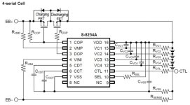
reliable 4s LiFePO4 bms, any recommendations?

shinyballs

1 kW
Joined
Sep 29, 2007
Messages
327
Location
Pacific NW
I am building someone a plug and play 12v pack connected to a 140W inverter. So, a minimum discharge current of 15A and a battery gauge or indicator light to indicate state of charge.
Anyone tried the BMSs from osn -
http://www.aliexpress.com/item/12V-4S-20A-BMS-PCB-PCM-For-4S-12-8V-LiFePO4-Battery-Pack/866600492.html
 
No experience with that model, but the specifications look like what you want.

I would suggest looking at Bestech Power:
http://www.bestechpower.com/pcmbmspcbforlifepo4batterypacks/

The guy there (Henry) has a good track record and will assist with the products. They normally like to deal in large volumes, so if you just want one, you may be lower on the priority list.

Normally when I deal with companies like this, I tell them I want an "engineering sample" for testing. Give them the impression that if you like it, you will buy 1000.
 
Thanks Richard, he emailed me a price list and will be ordering the 4S LiFePO4 PCM 15A (P/N:HCXD113V1), and test if it works ok.
 
There are very few BMS available for LiFePO4, so it will be great to have a test.

I have some model D126 that I have fully reverse engineered. If you want more current capacity, it may be possible to add FETs or replace them with higher rated ones. One nice thing about most of these is they have short circuit protection (but I would still use a fuse). If the short protection works properly and the fuse is sized right, you can stick a screwdriver across the output and nothing blows up.
 
I got a couple of their #HCX-D113V1 4s15A -
http://www.bestechpower.com/128v4spcmbmspcbforlifepo4batterypack/PCM-D113V1.html

It uses a Alpha & Omega Semiconductor AOD403 P-channel TO252 mosfet. Wired it to a Headway 4s3p pack. 0v on the load side ; probed the fets and no power from the drain legs. Is there another way to wire it?

Bestech emailed me this wiring diagram -
 

Attachments

  • blob.png
    blob.png
    40.5 KB · Views: 2,129
  • IMG_20150605_003802 - Copy.jpg
    IMG_20150605_003802 - Copy.jpg
    202 KB · Views: 2,129
  • IMG_20150605_003840 - Copy.jpg
    IMG_20150605_003840 - Copy.jpg
    330.5 KB · Views: 2,129
You could try measuring voltage from source to gate. FETs wont be on unless there is 5-10v there.
Also try measuring each cell separately at the board. If any one is out of the 'healthy' range, the BMS may be off.
 
measured voltage of FETS #1-3 :
Source & (B-) = 13.5V
Gate & (B-) = 13.5V
Drain & Source/Gate = 6.9V

Source, gate & drain in FETS #4-6 are all 0V

Voltage of each cells on the board are ~3.3V. (B-) & (B+) is 13.5V


fechter said:
You could try measuring voltage from source to gate. FETs wont be on unless there is 5-10v there.
Also try measuring each cell separately at the board. If any one is out of the 'healthy' range, the BMS may be off.
 

Attachments

  • blob - Copy.png
    blob - Copy.png
    131.5 KB · Views: 2,082
It seems half of the FET bank is turned off. The charge and discharge FETs are wired back-to-back in this configuration.

One thing to try is make sure there is nothing connected to the load when the cells are attached. If it 'sees' a load, it won't reset. Once the cells are all attached, then the load can be connected. Even if the inverter is off, there may be enough drain to keep it from resetting. Once it gets reset, it should be fine unless it runs low enough to trip, in which case disconnecting the load will be necessary again. With no load, you should see the pack voltage on the output terminals.

If this doesn't work, then I'm not sure what else to try other than a new BMS.
 
that makes sense. i would never have thought he was testing it with the invertor attached. if he actually measured those voltages on the BMS then it should be working. otherwise there could be an open circuit in the sense wires causing the output side mosfets to stay off.
 
Other than a multimeter to measure the voltage, no load has been connected to the output terminals. An odd thing is, 1 out of 10, when I disconnected the battery pack to the bms and reconnected, it is showing the pack voltage on the output terminals.

fechter said:
It seems half of the FET bank is turned off. The charge and discharge FETs are wired back-to-back in this configuration.

One thing to try is make sure there is nothing connected to the load when the cells are attached. If it 'sees' a load, it won't reset. Once the cells are all attached, then the load can be connected. Even if the inverter is off, there may be enough drain to keep it from resetting. Once it gets reset, it should be fine unless it runs low enough to trip, in which case disconnecting the load will be necessary again. With no load, you should see the pack voltage on the output terminals.

If this doesn't work, then I'm not sure what else to try other than a new BMS.
 
does the gate turn on when you put it on the charger after you have measured the gate to be turned off? if you have cell voltages in the proper range on each pad, and on the charger then both of the sets of mosfets will be turned on.
 
BMS only turns on when a charge is applied. HVC is around ~3.75V, haven't charged longer to see if balancing works.
Tried disconnecting everything and connecting again except the load ; still BMS does not turn on - i.e. no pack voltage on the output terminals. Will test the LVC next...
 
The chip markings on separate lines are -
8254aa
qvc500
14613

It could be one of the "found results" on mouser below:
http://www.mouser.com/_/?Keyword=8254aa&FS=True


fechter said:
Something's not right for sure.

Can you read the number off the chip in the middle?
 
Thanks, that's the chip on the board, it has 16 pins.
I tested the 2nd same bms with the same results - turns "on" only when a charger is wired to the output terminals.
 
P channel FETs, so -8v, but it seems the discharge bank is not turning on.

Unless the cell tap wires are mixed up, it would seem there's a problem with the board. I built a BMS test jig with a bunch of 1k ohm resistors in series that take the place of the battery cells. In your case only 4 would be needed. The resistors divide the voltage so each one has about the same voltage across it. By adjusting my power supply, I can put all of them in the normal operating range and measure the FET gate voltages and verify there is output. Dial the voltage down or up to test HVC and LVC functions.

I'd double check the voltages at the board for each cell and pay close attention to the polarity just to be sure the tap wires got connected in the right order.

It would suck if both boards are bad.

It might be good to try tracing the CTL and SEL pins to make sure they are wired properly. SEL selects 3 or 4 cells and should read high for 4 cells. CTL should be low.

One other thought: it's possible he mistakenly gave you boards made for Li-ion instead of LiFePO4. It would think all the cells were overdischarged.
 
Back
Top