Replacing Sealed Lead Acid (SLA) battery with LifePo4 Battery in home computer UPS

NSP

100 µW
Joined
Oct 22, 2023
Messages
8
Location
New Delhi
Hello,

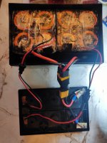
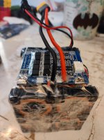
I have used two 12v packs, of 4 Serial connected 32700 3.2v LifePo4 6000mAh cells, connected in parallel (2P4S) to give theoretical capacity of 12Ah. I am using 14AWG wire for the battery connections. Each 12v pack is protected by 30amp 4S LifePo4 balanced BMS. This battery has been used to replace 7.5Ah SLA battery in a computer UPS. So far it is working very good and providing longer backup than SLA battery.

I have a few questions that I am still confused about and seeking input from everyone to figure out the answers.

1) Should I place a 30amp fuse on P+ port of the both BMS(s) or a 20amp fuse will be just fine?

2)Since the UPS is designed to work with 7.5Ah Sealed Lead Acid (SLA) battery, the charging voltage is set to 13.46volts(3.36v per cell) and can not be changed. I was doing some math, and figured, that at this voltage my LifePo4 cells will be 90% charged and therefore the Battery system will have actual capacity of 10.8Ah instead of the theoretical 12Ah that fully charged cells should have, since 90% of 12 is 10.8. Am I correct in my calculation?

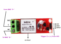
3) When there is a long power outage and the battery gets fully drained, UPS does not automatically start recharging the batteries when the power resumes as the BMS isolates the batteries to prevent complete discharge. I have added a manual momentary switch between B- and P- port of each BMS to manually restart the charging process if the batteries are in over-discharge-protected mode due to a long power outage. How can I automate this process? I am thinking of using a 12v Relay, with High level trigger, and connecting B- of BMS to COMMON port of Relay and P- of BMS to (NC) Normally Closed Port of the Relay. Trigger pin will be connected to 12v charging voltage coming from the UPS. So when there is 12v Power in the system the relay will be in "triggered" state and "(NO)" port will be in "closed" state and "(NC)" Port will be in open state. This way I think B- and P- will always be in shorted state as long as there is no power in the system as soon as there is 12v power in the system P- and B- will get disconnected. Will this setup work to automate recharge reset or can it damage the BMS?

Thanks in advance for your time.

Parts Used:
HX-4S-F30A (LifePo4 Balanced BMS/Blue PCB version) x2
LifePo4 Cells, 32700, 6000mAh, 3C, x8
14 AWG wire and XT-60 Connectors. x6 (3Male, 3Female)
Plastic Battrey case(150x98x94)mm
JST-XH 2 Pin connectors with wire x4 (2Male, 2Female)
Momentary push button switch x2

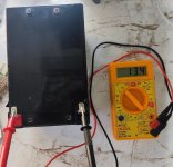
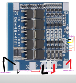
Here are some photographs:

Current Setup:
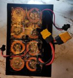
01 LifePo4 Batt-Pack.jpeg02 LifePo4 Batt-Pack.jpeg03 LifePo4 batt-Pack.jpeg04 LifePo4 Batt-pack.jpeg05 Circuit diagram on HX4SF30A.png

Proposed automation06 12V relay Circuit Diagram.png
 
1) Should I place a 30amp fuse on P+ port of the both BMS(s) or a 20amp fuse will be just fine?
What fuse does the UPS already have on the battery input?

If that fuse is less than the max rating of the BMS and internal pack wiring, and cells, then you can use another of the same rating right at the output of the pack (usually on the + tab), as close as possible to the output tab to protect as much of the system wiring as possible.

Remember that a fuse doesn't blow at it's rating; that rating is the point it is guaranteed *not* to blow below. So the maximum possible normal current your system will ever use has to be below this rating.

Above that point you have to check with the fuse manufacturer's data sheet to see the curve for current vs triptime, to know how long it will take to blow at a particular current, to know if it will actually be able to protect whatever parts you are trying to protect with it.

2)Since the UPS is designed to work with 7.5Ah Sealed Lead Acid (SLA) battery, the charging voltage is set to 13.46volts(3.36v per cell) and can not be changed. I was doing some math, and figured, that at this voltage my LifePo4 cells will be 90% charged and therefore the Battery system will have actual capacity of 10.8Ah instead of the theoretical 12Ah that fully charged cells should have, since 90% of 12 is 10.8. Am I correct in my calculation?
You'd have to look at the charge / discharge curve for your batteries to see what their actual state of charge (SoC) would be for that voltage, since it isn't a straight linear ratio. Almost all of the capacity of LiFePO4 (LFP) cells is within a tiny range around 3.2v, making voltage itself a poor indicator of SoC. If there is no data from the battery manufacturer, then you would have to check the manufacturer's data sheet for the actual cells used. If there is no data for those, then you can look up general LFP data sheets to guesstimate the capacity for a particular voltage.

A wattmeter is usually the most accurate way of verifying actual capacity.

However....the question isn't really capacity, it is runtime.

Does the system have enough runtime for you?
If it does, then none of that matters.
If it does not, you need more batteries in parallel.


3) When there is a long power outage and the battery gets fully drained, UPS does not automatically start recharging the batteries when the power resumes as the BMS isolates the batteries to prevent complete discharge.

With a Common Port BMS like yours, that has only one connection (P-) for both charge and discharge, then this shouldn't happen unless the cells are being discharged below the BMS LVC so that it thinks they are unsafe to recharge (or perhaps the cells are not tested and matched to each other so that there is at least one cell group that has so much less capacity than others that it drains like this, even when the others don't).


I have added a manual momentary switch between B- and P- port of each BMS to manually restart the charging process if the batteries are in over-discharge-protected mode due to a long power outage. How can I automate this process? I am thinking of using a 12v Relay, with High level trigger, and connecting B- of BMS to COMMON port of Relay and P- of BMS to (NC) Normally Closed Port of the Relay. Trigger pin will be connected to 12v charging voltage coming from the UPS. So when there is 12v Power in the system the relay will be in "triggered" state and "(NO)" port will be in "closed" state and "(NC)" Port will be in open state. This way I think B- and P- will always be in shorted state as long as there is no power in the system as soon as there is 12v power in the system P- and B- will get disconnected. Will this setup work to automate recharge reset or can it damage the BMS?
It shouldn't damage the BMS but it does bypass the BMS's protection whenever the relay is shorting P- to B-. So if there is anything in the system that can place a load on the cells, no matter how small, even without the system being powered on, it will drain the already-empty cells further with the potential to damage or destroy them.

If your BMS is not able to operate correctly and allow recharge, and you have already verified that at this state the cells are all above the BMS LVC (or safe-recharge point, if different), I would recommend using a circuit that only triggers the relay momentarily, just as you manually do this function.

A 555 timer chip could be used for this, in it's one-shot mode. Triggering would be done by whatever useful state change of the system happens when the BMS shuts off, such as the loss of gate signal to the BMS FETs, etc. Probably require a transistor or other buffer between the trigger signal and the input of the 555.
 
  • Like
Reactions: NSP
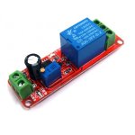
Thanks for the prompt reply and taking the time for such a detailed reply. For Question 1. my concern is circuit protection between the two parallel battery packs and I am thinking of using 20amp fuse on each BMS(s) B+ tab. For Question 2, this setup is giving me about 7 more minutes of run time over 7.5Ah SLA battery. For Question 3. I have ordered NE555 Delay Timer Switch Adjustable 0-10 Sec 12V Relay Module (Please see attached image) I am also attaching image of BMS specs and LifePo4 cell specs.ne555-delay-timer-12v-relay-module-800x800.jpgLifePo4 Cell Spec.pngHX-4S-F-30Amp info2 - Copy.jpg Again thanks for your time.
 
What fuse does the UPS already have on the battery input?

If that fuse is less than the max rating of the BMS and internal pack wiring, and cells, then you can use another of the same rating right at the output of the pack (usually on the + tab), as close as possible to the output tab to protect as much of the system wiring as possible.

Remember that a fuse doesn't blow at it's rating; that rating is the point it is guaranteed *not* to blow below. So the maximum possible normal current your system will ever use has to be below this rating.

Above that point you have to check with the fuse manufacturer's data sheet to see the curve for current vs triptime, to know how long it will take to blow at a particular current, to know if it will actually be able to protect whatever parts you are trying to protect with it.
Sorry, it took me so long to reply, but I was researching and trying to understand this stuff on my own. Currently there is no fuse that I can find between the wires going from BMS to the UPS PCB.

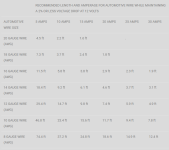
Since a 600VA(360 Watt) 220V-AC UPS can draw a maximum load of 30Amp(360W/12v=30Amps), and (37.2/2= 18.6) 18.6inch long 14AWG wire can safely carry 12V 30AMP current (as per the attached chart image), Therefore I am thinking of reducing the overall length of wire from the BMS to UPS PCB to 19 inches from the current 26 inches and placing a 30Amp fuse, somewhere close to the battery, in the circuit for wire protection.

Now, How does the BMS factor into this? BMS being used is 30AMP 4S LifePo4 BMS on each pack of four 32700, LifePo4, 3.2V, 6000mAh cells. I am assuming that the BMS will shut down each pack if there is a draw of more than 30AMPS so my circuit should be safe and have double safety if I also include an inline 30AMP fuse in the battery circuit.

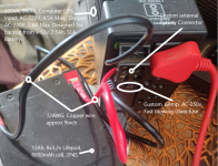
Strangely, the mains supply side (220-230v) also does not have any visible fuse, there is a Varistor (MOV-14D561K) on the PCB but no fuse, so I added a 6Amp-250v, fast blowing, glass fuse to the AC mains input wire as a precaution.

Please point out any errors in my assumptions/understanding of this circuit. and again thanks for your valuable time.01 12V DC Wire AWG_AMP_Length_Chart.pngCustom UPS Setup.pngScreenshot (352).pngBy the way this is the fuse (Pink one rated at 30Amps) I am considering for the circuit. One each right after the BMS. Color will also make Barbie happy 😜
 
Last edited:
Sorry, it took me so long to reply, but I was researching and trying to understand this stuff on my own. Currently there is no fuse that I can find between the wires going from BMS to the UPS PCB.

Since a 600VA(360 Watt) 220V-AC UPS can draw a maximum load of 30Amp(360W/12v=30Amps), and (37.2/2= 18.6) 18.6inch long 14AWG wire can safely carry 12V 30AMP current (as per the attached chart image), Therefore I am thinking of reducing the overall length of wire from the BMS to UPS PCB to 19 inches from the current 26 inches and placing a 30Amp fuse, somewhere close to the battery, in the circuit for wire protection.

Now, How does the BMS factor into this? BMS being used is 30AMP 4S LifePo4 BMS on each pack of four 32700, LifePo4, 3.2V, 6000mAh cells. I am assuming that the BMS will shut down each pack if there is a draw of more than 30AMPS so my circuit should be safe and have double safety if I also include an inline 30AMP fuse in the battery circuit.

Strangely, the mains supply side (220-230v) also does not have any visible fuse, there is a Varistor (MOV-14D561K) on the PCB but no fuse, so I added a 6Amp-250v, fast blowing, glass fuse to the AC mains input wire as a precaution.

Please point out any errors in my assumptions/understanding of this circuit. and again thanks for your valuable time.By the way this is the fuse (Pink one rated at 30Amps) I am considering for the circuit. One each right after the BMS. Color will also make Barbie happy
Sounds correct to me.

If the BMS has current sensing (should be a shunt or resistor in the current path, usually on the B- or P- side), tehn it should shutdown beyond some specified current and duration, which should be in it's specs if there are any. (they don't all have complete specs available)

The MOV is usually wired across ground to hot on the AC input to suppress voltage spikes on the input line. Occasionally they use something like it as an ICL (usually an NTC that decreases resistance the hotter it gets, so it starts out with high resistance to keep input current low as AC-side filter capacitors charge up when plugged in).; common on SMPSes.
 
  • Like
Reactions: NSP
Back
Top