Sabvoton 72100 mosfet equivalent

Joined
Jul 27, 2023
Messages
5
Location
Houston, TX
I have a new Sabvoton 72100 controller. On my first ride, I rode about 4 miles to my destination. On my return trip I was pulling away from a stoplight in mode 2. Mode 2 tops out at 22mph with current settings. Basically trying to say I was on a leisurely ride. I heard a pop noise almost like I popped a chain. I wasn’t peddling and it wasn’t the chain. I then get a 30H error on the UKC1 display. Long story short, I pull the controller and find the blue and green phase wires are shorted to positive. I’m curious what could have caused this. Im also hoping you all can help me out to identify an equivalent mosfet. I think I’ve found the same one on Aliexpress, but I’m hoping to find an equivalent in the states. The only specs I’ve come across so far are it’s rated at 100v and 150amps, but can’t say for sure. Any help or input is greatly appreciated.

Here’s a pic of one of the mosfet:
IMG_2164.jpeg
 
Probably just my old eyes, but even zoomed in I can't read the numbers in the image well enough to tell what all of them are. If you can post as text what you can read from it, it would help us help you find an equivalent to those.

LInking to the alternate parts you've found so far may also help.

Cause of failure? Thoughts:

Note that if all the FETs in that half of that phase are not all identical, they won't share current equally, and so one or more will take more to all of the load, depending on the individual characteristics. That heats that one more, which if it happens fast enough with enough load on it can cause it to fail--then the next most loaded one may do the same thing with the sudden spike in load, and so on.

This is one thing that can cause such failures, but it is also a concern when replacing FETs--you are "safer" replacing the entire set of FETs on that half of that phase bridge with the same ones (from the same batch so they have the closest matching characteristics without you having to test them for that).

Another common problem is heatsinking--many controllers bolt the fets to a bar that is then bolted to the casing, and neither the bar nor casing are "flat" to each other in most cases, and they end up depending on heatsink paste (and air) to transfer heat from bar to case in what can be large areas, often with too few bolts to securely fasten the bar to case.and well and evenly distribute the heat from all of them out of the casing.


Another problem is that it's not uncommon for a product like this to be "rated" near or at the limits of the parts it's made of, so that almost any excursion beyond the rated product limits is too much for it to handle, but such excursions happen easily enough from either poor programming or wide-tolerance parts in sensing paths, etc. The designers might have specified better parts, but then beancounters buy cheaper ones, and....


I don't recall if this is an FOC controller, but if it is, and it isn't correctly setup for the specific motor inductance, kV, resistance, pole count, etc., it won't drive the motor correctly or efficiently, and may cause excessive heating in both motor and controller (and excessive current draw from the battery).

Even with a generic square/trap or sinewave controller, if the phase/hall wiring combination is not correct, the timing of driving the motor pahses will be wrong, and have the same effect as the above. Sometimes it even makes the motor spin *much* faster than it should, especially without a load, but may have a lot lower torque than it should when doing this...but still higher current draw, heating, etc.

Motor phase winding problems can also blow FETs; intermittent or slight shorts between windings and stator laminations can happen from poor manufacturing processes (I've got one here with this issue I repaired with CoronaDope but that doesn't always work).

Too low an inductance on a motor for a particular controller's design or timing can also be a problem .
The chip reads: K150E10NE across the middle, 058 in bottom left corner and 2107 in bottom right.

I’m not opposed to replacing all of them for something that is more up to the task. I’m just not sure what that would be. Maybe something from TI or other known manufacturer with a good reputation.

Good points and I suspect it was something in my settings. This was an NB Power kit bought direct from NB Power. 3000w 3T motor. When the kit was first hooked up, I could not get it to pass the hall sensor test. I noticed on the included jumper to connect the controller to the motor cable 2 of the hall sensor wires were crossed, so I switched them and the hall test passed on the first try. The only odd thing was the value for phase angle was 190 I think. NB power said it should be in the neighborhood of 63. The motor ran smooth and silent, so perhaps I should have tried some more combinations until the test resulted in the recommended phase angle.

Also, when I took it apart. Heat sink grease was inadequate in my opinion. The center section between the aluminum plate and case was dry on the case. The plate had paste, but clearly was not making good contact with the case. The connection with the mosfet to the plate had kapton tape between the feet and the thermal compound. I’m not sure if this is usual practice or not.

Thank you for your informative reply! I greatly appreciate it!
 
The chip reads: K150E10NE across the middle, 058 in bottom left corner and 2107 in bottom right.
I don't see a datasheet in a quick search, but this is the "next model down"
though I don't know how much different it is. Knowing that the original was a Toshiba it should be possible to find their original datasheet, even if one isn't available for the "clone".

You can also use the chat on digikey or mouser and ask them for the closest replacement they have to what you've got; they might be familiar enough with it to do so.
I’m not opposed to replacing all of them for something that is more up to the task. I’m just not sure what that would be. Maybe something from TI or other known manufacturer with a good reputation.
Just have to find the original specs so you get one that will be the closest match to the drive specs (presuming the drive hardware is made for those FETs; if it's not then there's no data to go on and you could try anything that meets minimum voltage and current and max resistance).


Heat sink grease was inadequate in my opinion. The center section between the aluminum plate and case was dry on the case. The plate had paste, but clearly was not making good contact with the case.

If the plate / bar paste was not transferred to the case, then the bar is not touching the case there, and is not transferring any heat to the case along that entire surface area that isn't touching. This is not uncommon, and is usually because of a bent bar or non-flat case extrusion, and requires re-machining or lapping to fix if necessary. Sometimes you can fix it by adding more bolts between the two along the length of the bar, thru the case, but it may just deform the case skin locally to the bolt head and not force the two toegther along their entire surface area as desired.

The connection with the mosfet to the plate had kapton tape between the feet and the thermal compound. I’m not sure if this is usual practice or not.

The tape is there to prevent electrical shorts between phases; sometimes they use grey silpads instead, because kapton is VERY thin and easily damaged...if there is any electrical contact from FET to heatsink and the heatsink connects to any other FET in a different phase, or any other electrical potential relative to what is on that FET, you can get POOF. :(


Heatsink paste should be practically not there, because it is only intended to fill any teensy tiny air gaps in scratches and surface defects (because it's better than air by far, but not as good as metal-to-metal contact).

If you look up various pages on overclocking CPUs, or power amplifiers, etc., stuff that has to get rid of a LOT of heat, you'll find various methods of application, but essentially if the surfaces are correctly manufactured and parallel to each other, and actually flat, you only need to scrape enough grease on there to fill the surface scratches, and then when you mate the surfaces metal will touch metal everywhere it can, and metal to grease to metal where it can't.

If the surfaces are not correctly made, they could have large areas that will never touch, and the grease has to fill those gaps...but grease often dries out over time and contracts, leaving air gaps which are great insulators, reducing the heatsinking ability of the system. So the greater the metal-metal contact is, the better. There's a technique called lapping that can correct poor fit, but it's tedious and time consuming and not usually necessary (but helpful when there are really badly fitting surfaces).

If you can't tell if they fit, and you can't fix it, then it's safer to apply a thin, even coat of grease to one surface, so you can't see the surface and the ohter surface you scrape with grease-covered plastic sheet (credit card, etc) to just fill it's defects. Then clamp both surfaces together with their mounting bolts, and hope they make sufficient contact and have enough evenly applied force to squeeze all the excess grease out from between the metal surfaces so they make as much direct contact as possible.

How much practical difference any of it makes depends on how much heat is really generated, and how much sinking ability the outside air has (> difference in temperature = better, > airflow = better). If ther'es lots of cool air flwoing and not much heat generated, you could prbably leave it with no grease and a poor fit and be ok.....

Whle I did plenty of lapping/cooling mods/etc for CPU overlocking a couple decades ago, the most I have usually done on a controller was "safer" method I noted up above, but I haven't had one overheat and cause problems to require more (had one explode it's FETs from overload in a motor-stall test, but I don't think heatsinking had time to get heat out even if it was perfect; the controller just wasn't designed with proper safety limits).
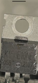
 
This specific MosFet may be made for the Chinese market only, so not on offer at the reliable places like Mouser, DigiKey etc.

The ones you dug out look like "reconditioned" from garbadge electronics. Better don't ask where and how they are sourced...
Our Chinese friends like to put key components from gear that failed into new products. Probaply more common than using anything new there.
You should be able to find some parts made for inverter use, with compareable amps, volts, switching at 5 Volt in a TO_220AB pack.
Maybe some IRFBxxxx MosFet's can be used. Will cost you something like 2-3$ a piece. Watch out for the legs, not all have identical logic.

Change all 24 if you do not get an identical replacement. I don't know the controllers reputation, 100 or 120Volt type could make it more reliable. The Amps are not that critical.

PS quick search found IRFB4110 as possible replacement, but get another opinion and try on your own risk, I'm no specialist in this field
 
Last edited:
Ok, I’ll take a look. I suspect my problem may have more to do with the phase angle setting. I took another look at my notes and NBpower said phase angle should be around 51. After hall sensor test, the controller set phase angle at 190. It seemed to run fine. Motor was dead silent and smooth. I was only 1 minute into my return trip in mode 2. Very light throttle when this happened.

NB has finally agreed to ship me a replacement, if I pay for shipping.

Im thinking I should work through the phase and hall sensor combos until the test returns an angle close to their recommended value.
 
Back
Top