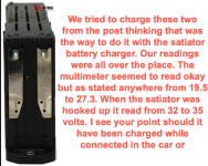
SATIATOR BATTERY CHARGER & 30 VOLT HYBRID CELL HYUNDAI KIA CHARGING ISSUES. PLEASE HELP IF YOU CAN.

ruavol2

10 µW
Joined
Nov 2, 2022
Messages
5
I have a Hyundai /Kia Sonata Hybrid Battery. The cells are 30 volt Lithium
I purchased a Grin Technologies Satiator Battery Charger Standard 12v to 52v
The purpose was to refurbish my own Hybrid Battery which was failing. Two of the batteries were very weak and after sitting a year 4 more swelled to big to fit in the enclosure. So replaced all of them.
I used a multimeter on the batteries that had dropped a little in voltage as I hear the goal is to get all cells at an equal level.
Used the multimeter setting 10 Meg Ohm Input DCV some of the battery cells which had a 19.5v to 21.5 up to 25.5 and 27.3 based on the MM readings.

Setup the Satiator Profile with the following.
We connected everything up and have the 30 v Lithium batteries connected to the Satiator and created a profile.
Lithium
VOLTAGE OF BATTERY = 30 V
AMPERS = 4.0
TRICKLE WAS SET AT AROUND 15 = I think the unit sets this itself?
END VOLTAGE = 27.3 WHICH IS WHAT WE ARE TRYING TO SET ALL THE BATTERIES TO

WHEN WE HIT START OR "FORCE START" THE BATTERY SHOWS ANYWHERE FROM 32.5 VOLTS TO 35.5 VOLTS ON EITHER OF THOSE BATTERIES.
THEN IT SHUTS OFF AUTOMATICALLY LIKE THE BATTERY HAD REACHED THE GOAL OR SETTING OF 27.3 OR GREATER.
IT DOES THIS FOR ALL OF THE BATTERIES NO MATTER THE VOLTAGE. COULD NOT GET HELP AT ALL EVEN WITH EMAIL FROM GRIN TECHNOLOGIES EBIKE.CA. I GUESS MY $400.00 PURCHASE DOES NOT WARRANT A CALL BACK FOR SUPPORT. GEESH! IS THIS FUNCTION NORMAL OPERATION? ALSO......

DOES THE SATIATOR READ THE CORRECT VOLTAGE FROM THE BATTERY POSTS POS + AND NEG - WHEN IT IS STARTED?
ALL THE BATTERIES DID THE SAME EXACT THING. VOLTAGE BOUNCED AROUND AND ALL READ GREATER THAN 30 + VOLTS
HOW DO I KNOW WHICH READING IS CORRECT OR IF THE UNIT IS CHARGING OR THE CELLS DO NOT NEED A CHARGE.
VERY CONFUSING.

I AM WILLING TO PAY ABOUT $60.00 PER HOUR FOR SUPPORT TO GET THE HELP I NEED. NO ONE AT JUSTANSWER.COM COULD HELP. I AM DESPERATE FOR ANY ADVICE YOU CAN OFFER. FEEL FREE TO CALL US IF IT IS EASIER. WE NEED TO GET THIS HYBRID BATTERY BACK ONLINE. PLEASE HELP. THANK YOU.
ROB BURDINE
919-272-1400
 
If the battery packs are 30volts, then they are created by seriesing a number of cells.

Usually when this is done in an independent battery pack, there is a BMS module on each pack that monitors each cell (or group) in the pack and either allows or disallows charge or discharge based on their status. How the module (if there is one) may be designed to work on your battery packs I don't know, but it is likely something that communicates with a master module in the car and asks it what to do, and if it can't talk to it it doesn't allow charge / discharge. (same if it gets a command back to not do so).

If this is the case, you may still read a voltage on the port, but it is high enough resistance that it won't pass current, so when you apply a charging voltage (force-start teh satiator) it will jump around in voltage as it attempts to connect to the battery cells and charge them, but is unable to.

In this event you typically have to open the battery pack to get to the actual cells inside it, and connect to the main + and - terminals of the cell stack itself, rather than any electronics that may be on the pack.

WIthout knowing the specifics of your actual battery packs / modules I don't know if that's even possible to do, but if it is, you could try measuring voltage there at the cell stack first, to see if it is different than at the battery pack's main connection. If it is, it's likely the BMS in the battery pack is preventing charge for whatever reason, and connecting the charger to the cell stack directly would allow charge.

If the BMS is preventing charge because of a problem it has detected in the stack, then this is not safe and could result in a fire, or in cell damage that could eventually lead to a fire, so don't do this unless you are certain there is no problem that could lead to this.
 
When you say get into the cells itself. We opened the battery casing and individually extracted the cells 9 of them 30 v each or 270.

HyundaiSonataKIAOptimaHybrid 30vBatterywithPOS_NEGPosts.png

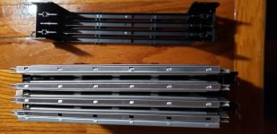
Or are you referring to 4 going in and charging the 4 square aluminium encased parts inside the 30 v seen below.

HyundaiSonataKIAOptimaHybrid30vBatterySideView.png

Thank you so much for this help. Any and all advice help appreciated. Feel free to call me I can pay about 60 an hour for phone support feel free to hide your phone number as private if you wish.
Rob
 
This is something much better worked out here, with text and images, rather than a phone call, especially for me since I don't do realtime interaction very well with situations like this--there's too much information to keep track of, etc. :oops:

Some educated guesses, without specifications and details on the units you have there:

If they are lithium cells, there are two common types. The least likely is LiFePO4, which is about 3.2v nominal. The other is about 3.7v nominal (some as little as 3.6v nominal). There's other variations, but these are teh two most likely.

So a "30V" cell, if 30v is it's nominal voltage rather than full, would have 8 cells in series inside each unit you have there, for a probable nominal voltage of 29.6v, and a possible full voltage anywhere from 32v (4v/cell) to 33.6v (4.2v/cell). Most cars dont' fully charge their cells (to lengthen useful lifespan) so it's more likely to be in the range of 32v fully charged per unit.

Note that if there are 8 cells in there, and they are not LiFePO4, then the units at 19.5v are overdischarged and have damaged cells in them, since 19.5v / 8 is about 2.4v / cell, whcih is below the safe discharge limit, assuming there is no electronics module blocking direct cell access for readings.

If 30v is the full voltage, then assuming about 4v/cell, it doesn't divide evenly into any number of cells of the kinds I'm aware of, so you'd have to find out what they are from the place that sells them.

If the place that sells the units has more info about this I'd recommend getting that info from them and posting it here, as it will help us help you correctly charge / test these without damaging them.

If these cells are like those used in some of the Leaf cars, each metal box contains two cells inside it, wired in series. That would make 8 cells for four metal boxes if that's how yours are setup inside the black casing. There are a number of versions, as seen in the images here
https://www.google.com/search?q=leaf+cell+module&tbm=isch


If there is no electronics module on these units (inside the black casing) that connects between the accessbile outside pair of terminals and the cells themselves, then the problem is not the one I described.

If there is an electronics module on these units (inside the black casing) that connects between the accessbile outside pair of terminals and the cells themselves, then the problem could be the one I described.

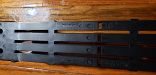
You'd need to open the black casing to find out if there is anything other than the cells themselves in there. Some of these casings are not designed to be opened, and may not reassemble once disassembled, so your best option for exploration is to use one of the failed units already removed from your car, and not your new units.

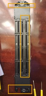
If you take good, well-lit, clear, in-focus, pictures at medium to high resolution of the actual unit you're going to open up, from all sides, we might be able to help you determine how to open it without damage, to see if there is an electronics module inside, and if so how to then access the direct cell connection(s) inside. I suspect it has fasteners at the points marked with red arrows below. The blue arrow points to the connector that probably goes to an electronics module inside the unit that is controlled by the car's master electronics (or a module in the main battery pack housing).
HyundaiSonataKIAOptimaHybrid30vBatterySideView.png

When I google around for info on the actual cells, internals of the units, etc., I don't find things that match what you have pics of here, for anything that has the details we need, so unless you have a link to such info, it's going to require opening the black casing to do this.


While it's open you can also take more good clear well-lit / etc pics so we can discover how it is wired inside, and how many cells are actually inside, which may help tell you the voltage the unit needs to be charged to.
 
Here are the specs of the battery image lower right.
2011HyundaiSonataHybridVehicleSpecifications.png

Lookn down into the cavity of the top of the battery and it appears there are 8 of the packs inside each Cell. There are a total of 9 30 V batteries for a total of 270 Volts.
20221104_002916.jpg

I read LG Chem , Tyco Electronics & PA66-TD30 or maybe TO30?
20221104_003218.jpg

Thank you for your help. I will donate to the charities in you posts. I hope I got you the right information this time. I am wondering if we should pull the battery cells back out of the encasement and try to recharge and if so do I have to pull those 4 packs out or can I plug the satiator into the posts for charging? Or do I have to pull those 4 packs out divide the two pieces out inside ( 8 ) and somehow charge them individually. If so how do I charge them that way? Thanks again. Rob
 
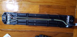
I forgot to mention, I have tried opening it from the bottom and I am either dumb as a fence post or This has some kind of real trick to opening. Probably for some really good reasons. Do you know how this thing should ope. Hoping I wont splash some kind of acid on me by trying. Here is the picture from the bottom.

20221104_104841.jpg
 
Here is the best shot I have of the bottom of the battery flipped upside down. I could get some access but seem stuck on how to remove those wire connectors. I see no release mechanism. Do you. If I have to pull those individually and they come off of the low voltage batteries. Do I create a profile on the satiator battery charger that limits the charge to what I call " one of those pack things (with the two packs in the one aluminium containers) and charge them to either 3.2v or 4.0 v each?
Any further advice much appreciated. ONe of your charities is going to have a decent day of fund raising that is all I can say. Thanks man...20221105_114454.jpg
 
Sorry I haven't gotten back to you on this yet, been working overtime and too wiped out to think technically at the moment, maybe after I have a nap (otherwise, tomorrow, probably).

Until I can take a fresh look at it, all I can say is it looks like there's no electronics in there, and all it has is direct cell connections--each of the little wires looks like it is a "sense" wire, often called a "balancing" or "balance" wire, that would generally go to the positive of each cell in the unit--if so, there should be 8 of them, plus a 9th ground (negative) wire.

If this is the case, then the main + and - terminals on the outside are actually the real main battery terminals on each unit, and the Satiator should be able to charge the unit as a "bare battery". So it will take me some more thinking on why it might not, and what you can do there to test further without risk of damaging anything.

Unfortunatley the Satiator only goes down to about 12v I think, so you can't use it to charge just one cell or one pair of cells, but you can do 3 or 4 at a time, if necessary. I'll see if I can figure out directions for testing the cells first.

Which multimeter do you have? A picture of it's entire front will help me give you specific directions on using it to do some cell checks.

BTW, I don't have any charities in any of my posts or profile, just links to my music / etc., and the paypal link in my signature that helps get me stuff for projects, and extra snacks and dog food for JellyBean the Perfectly Normal Schmoo. ;)
https://twitter.com/PerfNormSchmoo
cuVTJ3cf_400x400[1].jpg
 
If possible, get some good clear well-lit pics (in sunlight if possible, as it makes cameras focus better than most indoor lighting) of all the parts you've shown above, but from all the available angles (top, bottom, both ends, both sides, and an angle down from a top corner; this will help us see as much as possible of each part so we can better determine what is or isn't in there and how they are setup, so we can make better directions for testing.

In the meantime:

If you can access the metal of the contacts the small colored wires go into inside the white plastic holders well enough to touch them with the tips of your multimeter probes, I would recommend setting your meter to DC Volts. If it's autoranging, it'll automatically change to the right value, otherwise choose 20VDC.

Place the black meter lead on the (terminal for the) black wire, and the red lead on the orange one right next to it. Write down the value you get.

Move the black lead to the orange one, and the red lead to the brown wire with black stripe a couple places over. Write down the value you get.

Repeat this to measure each pair of wires, brown/black-green/silver, green/silver-white/green, white/green-first wire at other end of unit (gray? can't see it cleraly enough), then that wire to yellow, then yellow-green, then green-red.

Then red-black (from one end of module to the other).

Post all these values, in that order.

That will tell us the values of each cell, plus that of the entire unit of 8 cells.

The red wire and black wire are almost certainly the main + and - wires to monitor the pack itself with, and the other 7 wires go to the + ends of each cell (except the "top" one that is measured at the main +).

Knowing what all the cells are will tell us if they are balanced (all the same voltage) and thus safe to just charge as a pack. If they are not all the same voltage, then they'd need to be individually charged or drained to all be equal before it is safe to just charge the whole thing.

Once we determine this pack's health, and a test procedure for it, then a charge procedure, then you can use the same methods with the other ones.
 
Back
Top