Shenzhen (ecrazyman) Controller Information

The7 said:
This test shows that the followings are NOT necessary the cause of the critical frequency:
1) the LP filter of the Hall signal, and
2) the data representation in the MCU.

The shows that the critical frequency depends on the clock frequency.
The rate of executing the programming instructions depends on the clock frequecny??

Sorry, but I would disagree with point 2) there. Surely the relevant data would all be in terms of clock cycles not absolute time.
Yes, it might be working with a number representing the supply voltage, but that has been shown to be not related to the problem.

Nick
 
Tiberius said:
The7 said:
This test shows that the followings are NOT necessary the cause of the critical frequency:
1) the LP filter of the Hall signal, and
2) the data representation in the MCU.

The shows that the critical frequency depends on the clock frequency.
The rate of executing the programming instructions depends on the clock frequecny??

Sorry, but I would disagree with point 2) there. Surely the relevant data would all be in terms of clock cycles not absolute time.
Yes, it might be working with a number representing the supply voltage, but that has been shown to be not related to the problem.

Nick

Tiberius,

Thanks for pointing out my overlook.

If the frequency is represented by the number of counts per clock period, then "the data representation in the MCU" would still possiblily be the cause.

Suppose the motor frequency is 325 Hz,
For 16MHz clock, if the no of counts for 1 clock cycle = 325 counts
Let 325 counts be the maximun counts in the counter.

Then for 24MHz clock, the no of counts for 1 clock cycle = 325 x 16/24 = 217 counts
This new clock gives a different data representation.
To reach the 325 counts, the motor frequency needs to be 487 Hz which is predicted by Fechter.

It would be great if Fechter could also try at a lower clock frequency.
 
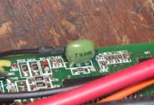
Here is the original 16mhz resonator on the 72V crazy controller pcb ...

Resonator.jpg
Replacement with this 20mhz resonator ...
http://search.digikey.com/scripts/DkSearch/dksus.dll?Detail?name=X909-ND
... would increase the critical frequency from 325hz to 325*20/16=406hz.

View attachment 1
Since the MCU is rated 20mhz it is appropriate for the resonator to operate at 20mhz also.
In all likelihood, a critical frequency of 406hz should be a high enough increase in clock speed to allow the Bafang to operate smoothly up to 88V.

BTW, The Bafang PMGR operates perfectly at 88V on my old analogue Crystalyte 72V 20-amp controller.
The no-load current never exceeded 0.90 amps at full throttle at 88V test voltage.
Analogue Crystalyte controllers are, of course, discontinued (go figure).

GEDC0269.JPG As soon as I lace up this motor I will be road testing it at 72V (nominal) and 20 amps w/ the old x-lyte.
Pics and vids to follow.

PS ... A bit of inspiration for you overclock (PUMA) enthusiasts ... http://www.sparkfun.com/commerce/present.php?p=Overclocking+a+PIC
(Inspiration provided by fechter of course)
I am sure Keywin would shit a pickle if someone 2X overclocked the MCU at 40mhz (use a crystal).
He just ain't that CRAZY! WTF F'n'A
USA #1
ha ha
 
Hi all, first off Great Forum lots of info, I live in the UK (Norfolk) have been using ebikes for the past year, about 5 months ago managed too get an Ezee sprint off Ebay (36 volt NiMH) the controller has blown so I decided to buy a ecrazyman 48V 18amp controller and some extra batteries to tune the 36 volt system into 48 Volt. Actuality I have been using 43 NiMHs which gives 62 volt fully charged. I use a forum http://www.pedelecs.co.uk/forum/ which has some pics and info on the bike http://www.pedelecs.co.uk/forum/electric-bicycles/1664-modded-sprint.html
The only colour code that worked was.
Controller Motor
Blue Yellow
Yellow Blue
Green Green
Hull wires
Black Black
Red Red
Green Green/Blue
Yellow *****
Blue Yellow
Below 7mph the motor is a little sluggish after that it’s smooth up to a NLS of 42mph.
On the road I can cruse at 26mph top speed of 30mph for around 20 miles, sometime when the throttle is opened I get what fells like a false neutral (No Power) by closing then opening the throttle again some times cures the problem, if that doesn’t work jabbing the front brake on then off again will cure it, if neither of these work the only solution is to stop the bike and roll it backward a few inches.
I decided to go for the Ecrazymans 48 volt 28amp controller to try and get this problem sorted.
Colour code worked out as,
Controller Motor
Blue Yellow
Yellow Blue
Green Green
Hull wires
Red Red
Black Black
Green Blue
Yellow Yellow
Blue Green
Runs smooth up to a NLS of 19mph then goes out of sync above that speed, after reading this tread its looks like the 325 Hz problem you’re having with the 72 volt controllers is happening with my 48 volt 28 amp controller with this Ezee motor, have just ordered a 24 Mhz 3 PIN CERAMIC RESONATOR off Ebay item no 270185419501 and will try that when it arrives.
 
Fetcher, can you tell me the frequency I will need the controller to support to be able to run my BMC (non hub) motor at 56 volts, without running into the problem?

Is it going to be at all possible with that MCU? And with going over 20mhz on it, would it be a good idea to add a heat sink?
 
aaannndddyyy said:
have just ordered a 24 Mhz 3 PIN CERAMIC RESONATOR off Ebay item no 270185419501 and will try that when it arrives.
Bro you are awesome! I have been looking for these! Overclock here I come!
http://cgi.ebay.com/ws/eBayISAPI.dll?ViewItem&item=270185419501&ru=http%3A%2F%2Fsearch.ebay.com%3A80%2Fsearch%2Fsearch.dll%3Ffrom%3DR40%26_trksid%3Dm37%26satitle%3D270185419501%26category0%3D%26fvi%3D1

So right now people who have this controller can modify it to work at higher critical frequency! :D
This fixes the problem with many geared motors.

The controller currently uses a 20-mhz MCU but only a 16-mhz resonator.
The resonator controls the clock speed of the MCU (just like in a PC CPU).
When combined with the MCU program code, the 16-mhz resonator produces a controller critical frequency of 325-hz.

The 16-mhz resonator is too slow. It is the main cause of the problem (other than sloppy code).

If a new resonator is 20-mhz, (0% MCU overclock) then the new critical frequency = 325-hz*20/16 = 406-hz.
This will solve the Bafang PMGR problem at 72V nominal.

If a new resonator is 24-mhz, (20% MCU overclock) then the new critical frequency = 325-hz*24/16 = 488-hz.
This will solve the PUMA PMGR problem at 36V nominal.

If a new resonator is 44-mhz, (120% MCU overclock) then the new critical frequency = 325-hz*44/16 = 894-hz.
This will solve the PUMA PMGR problem at 72V nominal. It may also kill the MCU or not "spark it up" at all. Oh well.

Maybe Keywin would please ask his pcb vendor to make some new boards with 40-mhz MCU and 44-mhz resonator or crystal oscillator?
There should be no additional cost to make it better and the code can stay exactly the same.

If a new resonator/oscilator is 44-mhz, and a new MCU is 40-mhz (10% MCU overclock) then the new critical frequency = 325-hz*40/16 = 894-hz.
This will also solve the PUMA PMGR problem at 72V nominal but in a safe and reliable way. 10% overclock is acceptable IMO.
Many PUMA owners would be oh so happy.

Toa Chie
 
Knuckles said:
The 16-mhz resonator is too slow. It is the main cause of the problem (other than sloppy code).

Maybe Keywin would please ask his pcb vendor to make some new boards with 40-mhz MCU and 44-mhz resonator or crystal oscillator?
There should be no additional cost to make it better and the code can stay exactly the same.

Well done!
Maybe this is the best workable solution if the vendor is unable to rewrite a better code/program for the MCU.
 
The7 said:
Knuckles said:
The 16-mhz resonator is too slow. It is the main cause of the problem (other than sloppy code).

Maybe Keywin would please ask his pcb vendor to make some new boards with 40-mhz MCU and 44-mhz resonator or crystal oscillator?
There should be no additional cost to make it better and the code can stay exactly the same.

Well done!
Maybe this is the best workable solution if the vendor is unable to rewrite a better code/program for the MCU.

Heck The7. You said this all along about the code. All I did was listen to you. Once fechter put a 24-mhz crystal on the pcb and overclocked the MCU we both knew you were dead on right!
The code is way too slow after all (it should be fixed - but that is a project for another day).

Toa Chie The7

USA is #1
USA is #1
USA is #1
 
I tested the overclocked controller with a Puma motor.
As predicted, the jitter starts happening right at 488hz. Exactly.

This corresponds to the full throttle speed at 44 volts.

Up until it hits the critical frequency, it runs smoothly with no nasty spikes.

So with a 24mhz clock, this would be a workable solution for system voltages up to 36v.

I don't think the stock MCU will be happy going much faster than 24mhz. With a PIC18F series processor, the same code will work, the pinout is the same, and we can clock up to possibly 44 mhz, which should work for a Puma up to 80v max (72v system).
 
I wish to thank fechter, The7, Tiberius and everyone else for working together to finally solve this PUMA mystery.
Like I said in my very first ES post ... "I am a ChE but I didn't know shit about ebikes until I started reading this forum."
http://endless-sphere.com/forums/viewtopic.php?f=2&t=4109

In my ignorance I recently asked fechter ... "So I am ignorant ... is the "analogue" v "digital" thing an issue of hall signal processing to control firing of the fets?"

fechter took the time to educate me and gave me this great answer ...

QUOTE

"If you upgrade the FETs in the old analog controller it will run much cooler.

The analog controller takes the hall signals and uses analog chips to derive the commutation sequence and the PWM. There are some dedicated brushless motor control chips available today that work like this (MC33035). There is no software, everything is done with hardware, making it extremely fast. The controllers [REDACTED] was getting from the manufacturer were made like this. They had other problems apparently.

The digital controller takes the hall signals and feeds them into a microcontroller unit. The throttle, low voltage signal, current signal, everything, goes into the MCU. The MCU uses software to process all the inputs and generate an output that looks like the analog one. All the adjustments, features, and limits can be done in software.

The "advantage" to the digital controller is the MCU is very cheap and very few other components are needed to make a controller. It's also easy to change the features by changing the software. Typical R/C controllers use this approach and seem to be quite reliable. If done properly, it works well. It is the way of the future.

I think if Keywin could find a faster processor and just substitute it for the one in there, it could go much faster ... The existing processor is clocking at 16 mhz but it is rated for up to 20 mhz (or at least the official Microchip version). It might be possible to increase the clock frequency by changing the ceramic resonator (like a crystal). I'm not sure what happens if you overclock it too much. Going from 15 to 20 mhz might give you enough speed to run the Bafang at 72v.

Let me see if I can find a faster crystal. Those are cheap ... "

END QUOTE

So you can see that fechter nailed the problem thru experimentation.
He did this by verifying the code theory as originally offered by The7.

I am lucky to know such a great group of intelligent people (endless-sphere) ... from all over the planet.

toa chie
Knuckles
 
No longer necessary to "bust balls". Keywin is working on implementing a new MCU for the controllers!

cheers
 
Anyone is nice enough to try it on 25MHZ Please, Just want to make sure that it will run 24MHZ stable with enough room.
 
I searched a large section of my junkpile and did not find anything between 24 and 32mhz. I also tested at 40mhz using an oscillator can, but processor did not spark up. No luck at 32mhz either. That would be really pushing it anyway.

It does seem rock solid at 24mhz. The processor power consumption has not changed significantly, in fact it seems to have dropped slightly. Go figure...
 
computerpc101 said:
Anyone is nice enough to try it on 25MHZ Please, Just want to make sure that it will run 24MHZ stable with enough room.

Funny. You can only try it if you can find it and/or buy it.

Mute point anyway. Keywin is in for 110%. he is building it now. 24mhz. "no problem"

On it's way now direct from Shenzhen.

buxie

(buxie='de nada')
 
I did overclock some Atmel microcontrollor chips before, They are rated at 16MHZ and running fine with 20MHZ, some up to about 22MHZ. However, After 1 year working for 24 hours per day, They can run stable at only 20MHZ now, some of them down to 18MHZ.

I tested it with 27MHZ Xtal, It doesn't work. RIghtnow, It is running at 23MHZ Xtal and stable.

For 16MHZ, MY small Schwinn AL1020 (16" wheel) runs very strong up to 35KM/h @ 48Volts.
For 23MHZ, It runs very strong up to 50KM/h @ 60 volts
not bad for a this Tiny electric bike.

Thanks for whoever find this, good work.
 
Knuckles said:
I wish to thank fechter and The7 and everyone else for working together to finally solve this PUMA mystery.

Tiberius should also be named because his test results and scope pictures provide us with many good information for this finding.

The code in the MCU has an upper limit of phase frequency of 325 Hz when the clock frequency is 16MHz.
This controller will act as normal 6-step controller up to 271 Hz when viewing the waveform from Tiberus.

It seems that there is some kind of "wait times" between the execution of events (or instructions). Usually MCU uses a certain "no of clock cycles in a wait loop" as a "wait time". It is not necessary to execute the next event immediately if it is known that the next event will NEVER happened within a certain "wait time". The "wait times" between different events could be different.

If the "wait time"s is cause, then it is only necessary to shorten the wait time by reducing the no of clock cycles in the "wait loop".

1) Why the phase voltage start "squaring" from 271 Hz to 325 Hz?
Possible explanation using the wait time:-
The "wait time" for 120 deg conduction becomes so long that it extents the conduction period when the phase frequency exceeds 271 Hz.
At 325 Hz, the conduction period reaches 180 deg and the phase voltage becomes "square".
Between 271 Hz and 325 Hz, there should be no adversary effect except that the "square" waveform will have more "harmonic current" losses than the "trapezoidal" waveform (at 120 deg conduction).

2) What would happen if the phase frequency try to exceed 325 Hz?
If the phase frequency tries to exceed 325 Hz, the conduction period tries to exceed 180 deg.
If the conduction period exceeds 180 deg, both top-side FET and low-side FET of the same phase will be fired at the same. It will effectively provide a "short circuit" path and very large current will flow to damage the FETs.
Since Tiberus used PSUs with current limt at about 2A, it will only trigger the current limt without demaging the controller itself.
 
fechter said:
The processor power consumption has not changed significantly, in fact it seems to have dropped slightly. Go figure...

You actually measured the change in MCU power consumption from 16-mhz to 24-mhz? Man that is freaky!

Dang!

Does this have anything to do with the orange wire?
 
The7 said:
If the "wait time"s is cause, then it is only necessary to shorten the wait time by reducing the no of clock cycles in the "wait loop".

Refer to ... http://www.sparkfun.com/commerce/present.php?p=Overclocking+a+PIC

QUOTE

20 MHz Test:
If you look at the code, you will see a value inside the rs_wait function. The function dictates the baud rate. Depending on how many cycles the rs_wait loop goes through changes the width of the rs232 pulses - ie baud rate. For 9600 bps with a 20MHz crystal, this value is 36. Sho' nuff, we got hyperterminal to read the text that was being sent from the PIC.

END QUOTE

Does the controller MCU code require tuning to 'jibe' with the MCU (over)clock speed?

I have the code as a txt file btw
 
computerpc101 said:
For 16MHZ, MY small Schwinn AL1020 (16" wheel) runs very strong up to 35KM/h @ 48Volts.
For 23MHZ, It runs very strong up to 50KM/h @ 60 volts
Glad that you have also confirmed our finding because the speed at 325 Hz is about 37 km/h (not 32) in your AL1020 motor.

I think you should use 23 MHz clock because AL 1020 has a max speed of 40-45 km/h on flat using 48V with the analog C-controller.

Noted that you are in computer field. Glad if you could share your experience about the MCU.
 
solarbbq2003 said:
does v2 crystalyte controller have a resonator?

Nope. Don't see one. I suspect the MCU has an internal clock. It should be possible to find a datasheet for the MCU that would give clock information. Sometimes you can change clock speed in software.
 
Over in the thread titled," version 2 clyte information" in the last few posts, I see that Brett posted some MCU stats there. Instead of pasting everything here too, perhaps folks could look at the data and discern if an answer to the MCU being able to provide a "software upgradeable" solution to the "jitters"is possible, since it appears that the clyte controller may not have an external resonator to impose a change. Also interesting is the voltage input into the chip may have something to do with altering the clocking speed?
 
Hi Guys,

I have just done an experiment to confirm/investigate the clock speed/timing issue.

I removed the 16 MHz ceramic resonator and clocked the processor from a pulse generator. That way I can vary the clock speed over 0 to 20 MHz.

Running my motor/controller combination at "half" speed - ie., 36 V, full throttle - giving about 160 Hz rate on the Hall sensors. I find the following: As I reduce the clock speed it is ok down to 8 MHz, then the ramp on the motor drive disappears and it becomes a square wave. If I take the clock speed any lower, it all falls apart. The motor phasing goes wrong and there are nasty noises from it. On the good side, nothing breaks or catches fire.

At partial throttle much the same occurs.

It looks like previously, because I could only raise 84 V from the PSUs, that I was reaching the first signs of trouble, but was just short of the point where it really goes wrong.

At least now I have a way of investigating the limit point without having scary amounts of electrical or mechanical energy flying about.

I'll try to capture some traces and post them over the weekend. That's all for now, because I'm 8 hours ahead of most of you and its the magic time that my friends drag me out of the lab and off to the pub.

Nick
 
Back
Top